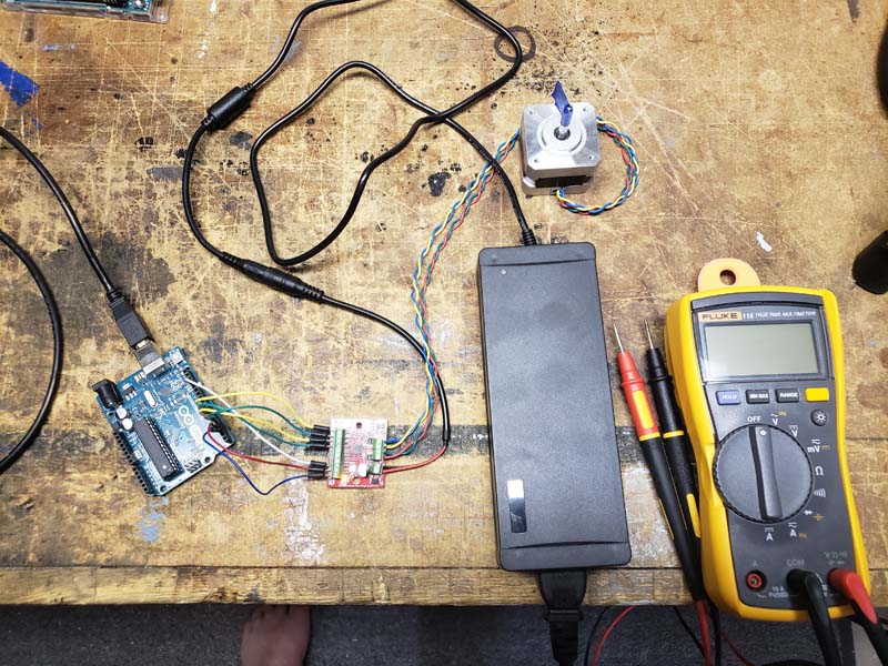
I just bought the SparkFun stepper motor 1568-1105-ND and the BigEasy driver 1568-1066-ND and hooked them up (see attached photos) to an Arduino Uno with a 24v 5A power supply for the motor and USB power for the UNO following the Big Easy Driver User Manual v1.2 (the board is v1.6a) instructions. I set the trimpot Vref to .29v (motor spec is .33A per coil) and ran the script supplied in the manual . All LEDs indicated power but no movement.
I then attempted to use the BigEasy Hookup Guide’s method of adjusting the trimpot by starting at OFF and slowly turning it up until you get movement from the motor. No movement. The motor heated up to approx 49C and the BigEasy board heated up mildly.
What am I missing here?
Most schematics with steppers and Arduinos use a shared ground. This could be causing some issues with communication.
@MavenScout
One thing you may want to try is to switch the wires of one coil of the motor. Sometimes the phase of one coil will fight with the phase of the other coil (especially when microstepping, like the BigEasyDriver does). So try swapping the red and green wires of the motor, or the blue and yellow.
Most interesting developments this morning.
First I reset the trimpot to .24v. (close as I could get to .29v)
Disconnected the white ground from the Arduino. Connected the 24v power for the motor and then connected the USB power to the Arduino. As soon as the power cable touched the Arduino socket the motor started a slow, jittery, arbitrary turning. Ran the test script. The motor would stop and do nothing DURING the code control. As soon as the code had finished, the motor would revert to the slow, jittery movement.
Reversed the grn/yel leads. No difference.
Replaced the white ground wire to the Arduino (with grn/yel leads still reversed). Motor doesn’t jitter or move. However, I noticed that whenever the code issued a new DIRection command, the motor would bump one step. That’s it.
Now what?
Did you reverse one set of coil lead? Or both? Only one set should be reversed.
Just the grn/yel leads, as noted.
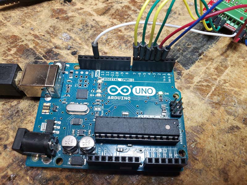
Ok. Looking at the second picture above, swap yellow and blue, and put green back where it was. The order would be yellow-blue-green-red (from top to bottom).
This is getting crazy. Same jittery motor, but option 2 and 4 of the script (2 = ReverseStepDefault, 4 = ForwardBackwardStep) cause the motor to stop completely until the subroutine is done and then the jitter resumes.
A picture is worth a thousand words…
https://youtu.be/WXD3c5G8gmI
Video comes up like this??
@MavenScout
Thanks for the video. That helps.
First: make sure that you have a common ground between the Uno and the Big Easy Driver. The signals coming from the Uno can be mis-interpreted by the A4988 chip on the Big Easy Driver without a ground reference.
Second: Try switching the yellow and blue wires. According to the hookup guide the wiring is as follows:
- A+ → Red Wire
- A- → Green Wire
- B+ → Blue Wire
- B- → Yellow Wire
The header connections on the board are layed out as such:

Third: Try altering the code from the guide so that there is a slightly longer delay between digital writes to the step pin, at least until you know you can get it to work. Sometimes the step signal is too quick, and the motor can’t catch up to the changing electrical fields. So anywhere there is a delay(1); you may want to change it to a delay(10);
If you look at the second pic in my OP that is the order it was in. You suggested in your first reply to try wiring it as it is currently connected. Each of which made no difference, as I reported. Not to mention that the documentation here on Digikey, and others, state that there is no polarity for the coils and that it doesn’t matter how it’s hooked up. Very confusing for a novice.
Also, I originally had a common ground connected as many sources state is best practice, for logical reasons, as well as Digikey’s own guide recommends. However, Robert_Fey suggested above that this may be the problem. And lo and behold as soon as it was disconnected the motor began to function, albeit erratically. Again, very confusing.
So now I’ll try adjusting the timing in the code and reveal what happens. Wish me luck I guess.
Altering the DELAY() timing in the code does nothing. Which makes sense now that I think about it. The erratic movement starts as soon as the Arduino is powered up. The script does not attempt to control the motor until the user selects an option from the menu. As soon as one enters 1, 2, 3 or 4 the motor stops! And then resumes it’s erratic movement as soon as the subroutine finishes.
Why is the motor trying to motate before the script even loads, let alone has not attempted to direct the motor to do anything. The motor does not attempt to move when the power is applied to the driver, only when it is applied to the Arduino. Not to mention, as soon as you ground the driver and the Arduino, nothing works!
Is this kind of difficulty indigenous to stepper motors? There are hundreds of web sites and videos showing it as simply plug-n-play. But my experience so far (this isn’t the first) has been nothing but headaches.
Am I doing something fundamentally wrong or is this just the nature of the beast?
A new revelation…
If I plug the power into the motor and simply touch the USB plug (from a laptop) to the outside of the USB socket on the Arduino, the motor starts moving. (?)
Connecting a jumper from the GND terminal on the bottom of the BED to the GND on the Arduino brings everything to a stop. Yet it all needs a common ground. So would connecting the GND of the 24v power to the motor to somewhere on the Arduino be more appropriate / make a difference?
To me this sounds like a noise problem. Would you be willing to copy the Arduino sketch into a post? I would like to verify that all of the pins are being driven.
//Declare pin functions on Arduino
  #define stp 2
  #define dir 3
  #define MS1 4
  #define MS2 5
  #define MS3 6
  #define EN  7

//Declare variables for functions
  char user_input;
  int x;
  int y;
  int state;

//=============================================================
void setup() {
  pinMode(stp, OUTPUT);
  pinMode(dir, OUTPUT);
  pinMode(MS1, OUTPUT);
  pinMode(MS2, OUTPUT);
  pinMode(MS3, OUTPUT);
  pinMode(EN, OUTPUT);

  resetBEDPins();                                     //Set step, direction, microstep and enable pins to default states
  Serial.begin(9600);                                 //Open Serial connection for debugging
  Serial.println("Begin motor control");
  Serial.println();

//Print function list for user selection
  Serial.println("Enter number for control option:");
  Serial.println("1. Turn at default microstep mode.");
  Serial.println("2. Reverse direction at default microstep mode.");
  Serial.println("3. Turn at 1/16th microstep mode.");
  Serial.println("4. Step forward and reverse directions.");
  Serial.println();
}

//=============================================================
void loop() {

  while(Serial.available()){
    user_input = Serial.read();                       //Read user input and trigger appropriate function
    digitalWrite(EN, LOW);                            //Pull enable pin low to set FETs active and allow motor control
    if (user_input =='1') {
      StepForwardDefault();
      } else if(user_input =='2') {
        ReverseStepDefault();
      } else if(user_input =='3') {
        SmallStepMode();
      } else if(user_input =='4') {
        ForwardBackwardStep();
      } else {
        Serial.println("Invalid option entered.");
    }
  resetBEDPins();
  }
}

//=============================================================
//Default microstep mode function

void StepForwardDefault() {
  Serial.println("Moving forward at default step mode.");
  digitalWrite(dir, LOW);                            //Pull direction pin low to move "forward"
  for(x= 1; x<1000; x++){                            //Loop the forward stepping enough times for motion to be visible
    digitalWrite(stp,HIGH);                          //Trigger one step forward
    delay(1);
    digitalWrite(stp,LOW);                           //Pull step pin low so it can be triggered again
    delay(1);
  }
  Serial.println("Enter new option");
  Serial.println();
}

//=============================================================
//Reverse default microstep mode function

void ReverseStepDefault(){
  Serial.println("Moving in reverse at default step mode.");
  digitalWrite(dir, HIGH);                           //Pull direction pin high to move in "reverse"
  for(x= 1; x<1000; x++){                            //Loop the stepping enough times for motion to be visible
    digitalWrite(stp,HIGH);                          //Trigger one step
    delay(1);
    digitalWrite(stp,LOW);                           //Pull step pin low so it can be triggered again
    delay(1);
  }
  Serial.println("Enter new option");
  Serial.println();
}

//=============================================================
// 1/16th microstep foward mode function

void SmallStepMode(){
  Serial.println("Stepping at 1/16th microstep mode.");
  digitalWrite(dir, LOW);                            //Pull direction pin low to move "forward"
  digitalWrite(MS1, HIGH);                           //Pull MS1,MS2, and MS3 high to set logic to 1/16th microstep resolution
  digitalWrite(MS2, HIGH);
  digitalWrite(MS3, HIGH);
  for(x= 1; x<1000; x++){                            //Loop the forward stepping enough times for motion to be visible
    digitalWrite(stp,HIGH);                          //Trigger one step forward
    delay(1);
    digitalWrite(stp,LOW);                           //Pull step pin low so it can be triggered again
    delay(1);
  }
  Serial.println("Enter new option");
  Serial.println();
}

//=============================================================
//Forward/reverse stepping function

void ForwardBackwardStep(){
  Serial.println("Alternate between stepping forward and reverse.");
  for(x= 1; x<5; x++){                               //Loop the forward stepping enough times for motion to be visible
//Read direction pin state and change it
    state=digitalRead(dir);
    if(state == HIGH){
      digitalWrite(dir, LOW);
    } else if(state ==LOW){
      digitalWrite(dir,HIGH);
    }
    for(y=1; y<1000; y++){
      digitalWrite(stp,HIGH);                        //Trigger one step
      delay(1);
      digitalWrite(stp,LOW);                         //Pull step pin low so it can be triggered again
      delay(1);
    }
  }
  Serial.println("Enter new option");
  Serial.println();
}

//=============================================================
//Reset Big Easy Driver pins to default states

void resetBEDPins(){
  digitalWrite(stp, LOW);
  digitalWrite(dir, LOW);
  digitalWrite(MS1, LOW);
  digitalWrite(MS2, LOW);
  digitalWrite(MS3, LOW);
  digitalWrite(EN, HIGH);
}
BTW the resetBEDPins() is missing from the Big Easy Driver Hookup Guide. I was able to Google it and find a copy.
A few notes about the hardware setup:
This is not accurate. Your original picture shows (top to bottom) B-Y-G-R. The suggestion was to connect it as B-Y-R-G. It looks like you’ve corrected it now to be the same as shown in the hookup guide which is R-G-B-Y.
Individual coils have no polarity. However, you should remain consistent across both coils so that the fields created by energizing the coils will be in the correct direction.
Lack of motion does not imply that the ground shouldn’t be there. As @ReidLandsrud pointed out, if there is no common ground, the driver doesn’t know how to interpret the voltage levels coming from the Arduino. The motor moves because the driver is seeing unknown signals on its inputs that may randomly trigger the outputs. There is no behavior defined for this case. You need to have a common ground for this to work properly.
As you mentioned, the Arduino does not try to control the motor until the user selects an option. So at start up, the motor should be still.
If you have a ground connection from the Arduino to the driver board, it is also connected to the ground of the power supply.
1 Like
Thanks for the help guys. I learned a lot in a short time. Moving on. Gonna try my hand at DC motor using PID. Wish me luck.