Created by Ben Roloff, last modified on Jan 22, 2019

Introduction
Now DC servomotors are made to be simple to drive. They are meant to be a device that can just be dropped in. Unlike a normal DC motor which needs extra circuitry. They are made up of a DC motor with built in h bridges and even some feedback loops. This allows for them to be an easily run dc motor if it is continuous or a positional motor that can move to a desired angle. The nice thing about simple servomotors is that They usually come with three wires. One goes to power, one to ground, and the third one is the signal. The signal which controls the angle or direction and speed is run of a simple pwm signal. This makes them a quick and easy motor to get started with.
Servomotors
The first thing to look at with the servomotor is the datasheet. Now some will have more data than others, but the biggest thing you should see is the info on the pwm signal. The PWM signal of most servomotors are around a 21.5 ms period and about a 7% duty cycle. Which means it is on for about 1.5 ms and off for 20 ms. This is usually position 90 degrees or stop on a servomotor. Increasing the on time above 1.5 will move the servo closer to 180 degrees or move clockwise. The opposite direction moves to 0 degrees or counterclockwise. The extremes are usually around 2.25 ms and 0.75 ms. This will change depending on the servomotor. The other big thing is after writing your code, you will need to test for how accurate it is to the ms and may have to adjust it to get a correct zero.
The Software
Arduino
Most microcontrollers have some timer that is setup to be able to create a pwm signal. If you are using an Arduino it is fairly easy to create the necessary signal using their IDE as shown here. Arduino has a built in servo library and a couple of example programs to get you started. Most microcontrollers don’t have that super of an easy setup, but in general a pwm signal is super short and easy code.
SCTimer
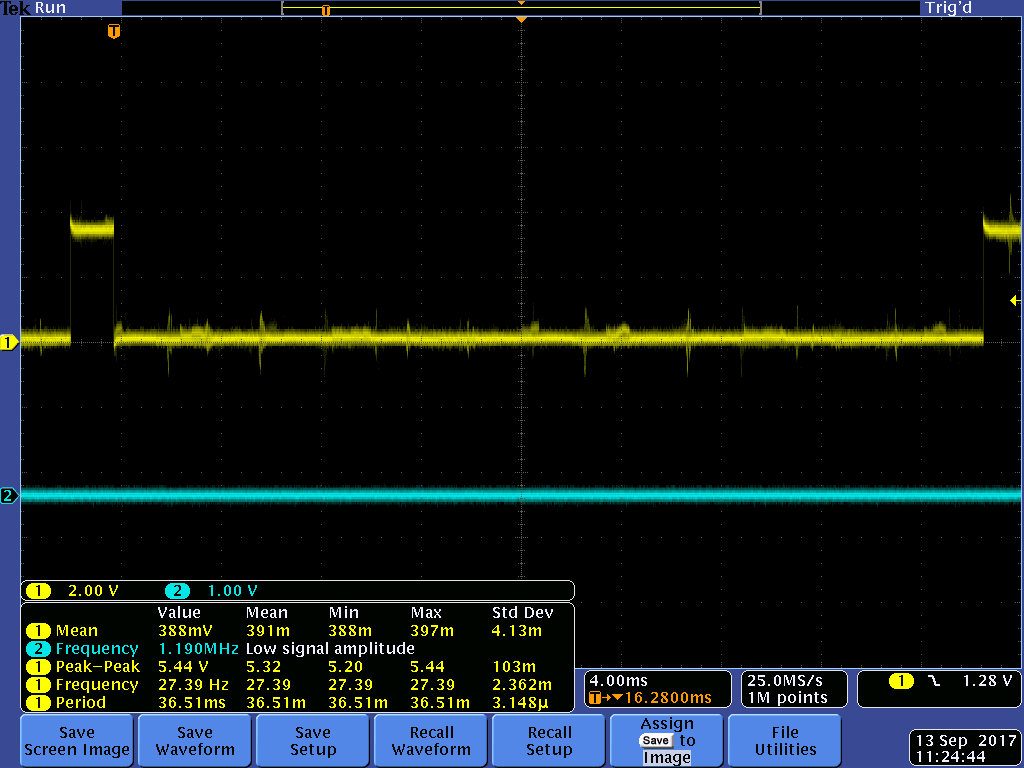
The LPC 812, for getting started with the LPC 812 go here, uses an SCTimer for its counter and pwm signal. This timer is a little more than most given that you are able to use different states. The other nice thing with this one is that you can use either a 32 bit timer or two 16 bit timers. It uses matches and events to curtail the signal. This allows you to easily make whatever signal you want and have preset changes based upon inputs. As seen in the code the big thing is setting up events and matches, once that is done it is easy to use. The big thing to make sure you do if you want to change one of the match values, is to use the reload variable. You can see the the output of the desired pwm signal on the oscilloscope picture below.
Servo_Init()
#define Count_ms 0.001*SystemCoreClock              // global variable for getting a ms value from the System Clock

void Servo_Init()
{
LPC_SYSCON->SYSAHBCLKCTRL |= (1<<8);           // enable the clock for the SCT
LPC_SYSCON->PRESETCTRL |= (1<<8);              // disable reset
LPC_SWM->PINASSIGN6 = 0x6ffffff;                 // assign SCT output 0 to pin 6
LPC_IOCON->PIO0_6 |= (1<<5);                       // this enables hysteresis

LPC_SCT->CONFIG |= 1;                            // use one 32 bit timer
LPC_SCT->CONFIG |= (1<<17);                    // autolimit with match 0
LPC_SCT->REGMODE_L = (0);                        // this makes all the match registers match and not capture registers
 LPC_SCT->MATCH[0].U = 21.5*Count_ms;             // set limit at off time of 20 ms and desired duty cycle of 1.5 ms
LPC_SCT->MATCHREL[0].U = LPC_SCT->MATCH[0].U;     // load the reload value
LPC_SCT->EVENT[0].CTRL |= 0;                     // set event 0 to match 0
LPC_SCT->EVENT[0].CTRL |= (1<<12);             // set event 0 to trigger on match
LPC_SCT->EVENT[0].STATE |= 0x1;                  // event 0 operates in state 0

LPC_SCT->MATCH[1].U = 20*Count_ms;           // set match 1 to the off time of 20 ms
LPC_SCT->MATCHREL[1].U = LPC_SCT->MATCH[1].U;     // load reload value
LPC_SCT->EVENT[1].CTRL |= 1;                     //set event 1 to match 1
LPC_SCT->EVENT[1].CTRL |= (1<<12);                 // set event 1 to trigger on match
LPC_SCT->EVENT[1].STATE |= 0x1;                  // event 1 operates in state 0

LPC_SCT->OUT[0].SET |= (1<<1);                     // output is set at event 1
LPC_SCT->OUT[0].CLR |= (1<<0);                     // output is cleared at event 0

LPC_SCT->CTRL_U &=~(1<<2);                     // turn off halt bit
}
Main()
Servo_Init(); // initialize the SCT pwm

while(1) {

for(i = 0; i < 300000; i++);                 // random delay
LPC_SCT->CTRL_U |= (1<<2);                     // turn on halt bit
LPC_SCT->MATCHREL[0].U = 20.75*Count_ms; // change reload of limit
LPC_SCT->CTRL_U &=~(1<<2);                     // turn off halt bit
for(i = 0; i < 300000; i++);             // random delay
LPC_SCT->CTRL_U |= (1<<2);                 // turn on halt bit
LPC_SCT->MATCHREL[0].U = 22.25*Count_ms; // change reload of limit
LPC_SCT->CTRL_U &=~(1<<2);                 // turn off halt bit
for(i = 0; i < 300000; i++);             // random delay
LPC_SCT->CTRL_U |= (1<<2);                 // turn on halt bit
LPC_SCT->MATCHREL[0].U = 21.5*Count_ms;      // change reload limit
LPC_SCT->CTRL_U &=~(1<<2);                 // turn off halt bit

}

TMR
Another common one to find is a TMR timer for the pwm signal. This is a basic timer. To create the pwm signal you usually set a period and duty cycle more on this style of pwm can be found here the relevant code is shown below. For this example the parts that would need to be changed would be your period and duty cycle.
PWM code for TMR
//This code was borrowed from http://www.eewiki.net/display/microcontroller/Getting+Started+with+NXP%27s+LPC11XX+Cortex-M0+ARM+Microcontrollers
//Author: Justin Clack

#include "LPC11xx.h"

int main(void) {

//Set up 16 bit timer for PWM operation
LPC_IOCON->PIO0_8         = (LPC_IOCON->PIO0_8 & ~(0x3FF)) | 0x2;     //set up pin for PWM use (sec 7.4.23)
LPC_SYSCON->SYSAHBCLKCTRL |= (1<<7);                                  //enable clock signal to 16 bit timer0 (sec 3.5.14)
LPC_TMR16B0->PR           = 0x0;                                      //set prescaler max value, not used here (sec 18.7.4)
LPC_TMR16B0->MCR          = 0x10;                                     //set for reset on counter match (sec 18.7.6)
LPC_TMR16B0->EMR          |= 0x20;                                    //set pin 27 to 1 on match (sec 18.7.10)
LPC_TMR16B0->CCR          = 0;                                        //set to timer mode (sec 18.7.11)
LPC_TMR16B0->PWMC         = 0x1;                                      //set channel zero to PWM mode (sec 18.7.12)
LPC_TMR16B0->MR1          = 0x32;                                     //set value for period (sec 18.7.7)
LPC_TMR16B0->MR0          = 0xC;                                      //set value for duty cycle (sec 18.7.7)
LPC_TMR16B0->TCR          |= 0x3;                                     //enable and reset counter (sec 18.7.2)
LPC_TMR16B0->TCR          &= ~(0x2);                                  //clear reset bit (sec 18.7.2)

while(1){                                                     //infinite loop
}
return 0 ;
}
Brute Force
You can make a dummy one using a gpio pin and timing yourself. Now this is a brute force way, that is not very precise and has a lot of drawbacks. Since the signal isn’t running separately from the rest of the code any other function calls or code within will change the timer. This means that either you have to account for all that, or this can be the only thing the code does, which is not very useful. You can see on the oscilloscope output that you can make the pwm signal, but it takes a little bit of work to make it a correct one.
GPIO_PWM_Init()
void delay_ms(int x)
{
int i;
for(i = 0; i < (x*1000); i++); // random delay to get as close as possible to a ms
return;
}
delay_ms Expand source
Main() Expand source
Conclusion
Servomotors are pretty easy to get going. They are probably the easiest electric motor to run. All that is necessary is a pwm signal. PWM signal generating is pretty common on most microcontrollers. This C code while not universal should be a good starting point atleast for your microcontroller. Driving servomotors is not rocket science, they are designed to be the easy to use.