Created by Shaun Gruenig, modified by Matthew Bon on Oct 07, 2016 and updated by Scott Raeker March x, 2021.
updated info from March 9, 2021: Silicon Labs comment “Bluegiga Legacy Bluetooth Low Energy (BLE) modules have been very popular in the market since launching in 2011 and are still in volume production today. However, for new Bluetooth 5 designs, we recommend our latest BGM13 Bluetooth Modules and BGX13 Bluetooth Modules, based on our EFR32BG SoCs.”

Purpose
This page explains how to set up the Silicon Labs BLE112 Bluetooth Low Energy module to communicate with a microcontroller via UART.
Quick Links
Purchase Links
- Silicon Labs BLE112 Bluetooth Low Energy Module
- Texas Instruments CC-Debugger - used for updating the firmware on the BLE112.
- Silicon Labs BLE112 Development Kit - useful for evaluation purposes; allows you to use the BLE112 without having to manual breakout the pins, and contains many other on-board devices
Reference Documentation
- BLE112 Documentation and Software - contains many useful resources to help with using the BLE112 module, including the SDK which is used in this tutorial and the reference guide for the BGLib API.
- Silicon Lab’s Forum search for BLE112 for Bluetooth Smart - contains lots of useful threads related to getting started and working with the BLE112.
- BLE112 Datasheet
Downloads
- BLE112 Breakout Board Layout - zip file containing the files needed to fabricate the breakout board we created for the BLE112.
Introduction
(Taken from the BlueGiga BLE112 product information page) The BLE112 is a Bluetooth Smart module targeted for low-power sensors and accessories. It integrates all features required for a Bluetooth Smart application, including Bluetooth radio, software stack, and GATT-based profiles. The BLE112 Bluetooth Smart module can also host end-user applications, which means no external micro controller is required in size or price constrained devices. More over, it has flexible hardware interfaces to connect to different peripherals and sensors and can be powered directly from a standard 3V coin cell battery or a pair of AAA batteries. In the lowest power sleep mode it merely consumes 500 nA and will wake up within a few hundred microseconds.
This tutorial will discuss how to establish communication between a microcontroller and a BLE112 module using BGAPI (which comes preloaded on the BLE112) and BGLib (a C library provided by BlueGiga used to interface with the BLE112 via an external device such as a microcontroller). BGLib contains most of the code necessary to interface with the BLE112; to make the library work with your microcontroller, you simply need to write a send function and a receive function that tell BGLib how to communicate with the BLE112 using a UART or USB peripheral on your microcontroller. In this article, we will focus on using a microcontroller’s UART peripheral to communicate with the module. To get a better background on how the BLE112 and BGLib works, or if at any point in the tutorial you need elaboration on something pertaining to the BLE112 or BGLib, I recommend looking at the links above under ‘Reference Documentation’. You will need to sign up for a free account on BlueGiga’s website to access some of the materials, but they are very useful in understanding how to work with the BLE112.
Tutorial
Here we will try to provide a clear explanation of how to get the BLE112 up and running for the first time.
Setting up the Hardware Interface
Breaking out the Pins
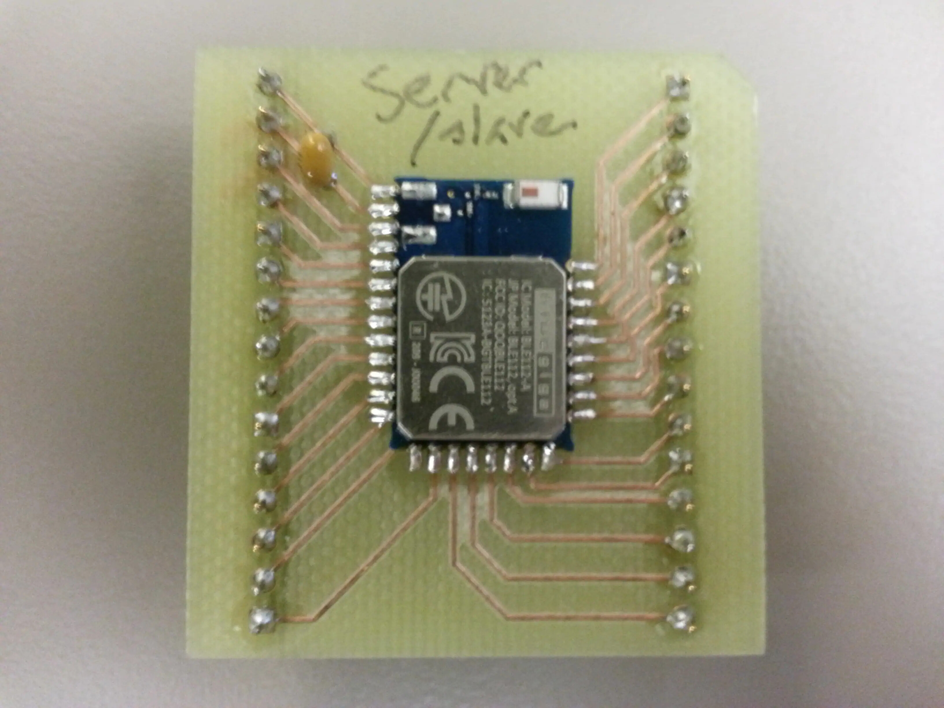
To begin communicating with the BLE112, we first need to breakout the pins so that we can connect to them using wires and a breadboard. To accomplish this, we fabricated a board to solder the module to. For those who do not have access to the equipment to do this, you may be able to simply solder wires to the contacts (look at wiring diagram below to see which pins we will be using). The Bluegiga BLE112 Development Kit also provides access to the pins on the BLE112 module. The land pattern on page 17 of the datasheet can be referred to if you would like to construct your own breakout board; this is the same footprint we used when making our breakout board, which is shown below:
The files to fabricate this board can be found in the Quick Links section above.
Updating the Firmware
Once we have the pins broken out, we will want to update the device’s firmware, since the pins that are programmed to communicate via UART depend on the BLE112’s firmware. Many (but not all) of the BLE112 modules come preloaded with the firmware for BlueGiga’s ‘UARTDemo’ example. Their examples and the C code for BGLib can be found here under Software ->Bluetooth Low Energy Software and SDK. In order to update firmware on the device, you will likely need to use TI’s CC-Debugger; this device makes updating the firmware very easy to do when used with BlueGiga’s BleUpdate program (which is included in the aforementioned SDK). For this tutorial, we will use the same pin setup as the ‘UARTDemo’ example, as this hardware layout (contained in the hardware.xml file) will work for most projects that use UART to communicate with the BLE112. For reference, here is the hardware.xml file contained in the ‘UARTDemo’ example:
‘UARTDemo’ hardware.xml
<?xml version="1.0" encoding="UTF-8" ?>
<hardware>
    <sleeposc enable="true" ppm="30" />
    <usb enable="false" endpoint="none" />
    <txpower power="15" bias="5" />
    <usart channel="1" alternate="1" baud="57600"  endpoint="api" />
    <wakeup_pin enable="true" port="0" pin="0" />
    <port index="0" tristatemask="0" pull="down" />
    <pmux regulator_pin="7" />
</hardware>
As you can see in the xml above, UART channel 1 is enable (specifically, channel 1, alternate 1). Looking in the datasheet (screenshot below)

we can see that this sets up P0_4 as Tx and P0_5 as Rx. The default communication mode of the BLE112 has flow control turned on, which is what the RT (RTS - ready to send) and CT (CTS - clear to send) pins are used for. Unfortunately, many UART peripherals do not have flow control. Thankfully, the BLE112 includes something called ‘packet mode’, which disables flow control, and instead requires you to specify the size of the packet you are sending to the BLE112 module. This tutorial will use packet mode, so we will want to modify the hardware.xml file, specifically the line that starts with “usart channel”, as shown below:
hardware.xml modification
<usart channel="1" alternate="1" baud="57600" endpoint="api" mode="packet" flow="false" />
This turns flow control off and sets the mode to packet mode. Now when we define our function to send data, we will have to first send the number of bytes contained in the packet (BGLib makes this quite easy; we will cover this more in depth in the software portion of the tutorial). In order to send this modification of the hardware.xml to the BLE112, we will need to use the CC-debugger and BleUpdate.
Wiring the Module
Once the firmware has been updated, we can connect the microcontroller’s UART Rx pin to the BLE112’s UART Tx pin, and the MCU’s Tx pin to the BLE112’s Rx pin. UART communication requires the data lines to be held high when idle, so we should add 10K pull-up resistors on each line as well (as shown below). From reading the datasheet we can find that the reset pin is active low. If you would like to be able to reset the device in this manner, you can use a GPIO pin on your microcontroller to control this pin. Since the BLE112 can also be reset via software commands, we will just tie the reset pin to power for this tutorial. In the hardware.xml file, we also see that pin P0_0 is setup as the wake-up pin. So that we don’t have to worry about the BLE112 going to sleep while we try to communicate with it, we will also tie this pin to power. You may need to tie certain pins to ground or 3.3V to avoid current leakage, but for simplicity, we avoid doing this in this tutorial (more information can be found in the datasheet). A complete pin connection diagram is shown below:

Setting up the Software Interface
Connecting BGLib to Your UART
To begin setting up the software interface, we first need to include the BGLib C libraries (found in the SDK) in our project code. There are four files that are necessary: ‘commands.c’, ‘cmd_def.c’, cmd_def.h’, and ‘apitypes.h’. These contain almost everything you need to communicate with the BLE112 (regarding software). However, since these libraries are set up to work with any microcontroller with a UART or USB interface, we need to tell the libraries how to communicate with our particular microcontroller’s UART peripheral. We need two functions: one to tell the libraries how to send data via UART and one to tell the libraries how to read data via UART (or USB, but this tutorial will focus on communication via UART).
Send Function
For the send/output function, there is a function pointer that needs to be pointed to the send function you write. It is defined in ‘cmd_def.c’ as:
Send Function Pointer
void (*bglib_output)(uint8 len1,uint8* data1,uint16 len2,uint8* data2) = 0;
So we need to define our send function to have the same arguments and return type. Here is some basic pseudocode of what your function might look like:
Send Function Pseudocode
void output (uint8 len1, uint8* data1, uint16 len2, uint8* data2)
    //since we are using packet mode, we need to begin every packet with the size of the packet
    send character(len1 + len2)

    //send bluetooth message header
    for i = 0 to len1
        send character(data1[i])

    //send bluetooth message payload
    for i = 0 to len2
        send character(data2[i])
Here is an example of a send function written for the TI Tiva TM4C123GH6PM microcontroller which allows communication with the bluetooth module over its UART 5 peripheral:
UART Send Function Example
//this is the callback function which tells the BLE API how to
//send messages via the 123G's UART peripheral library. The messages
//are sent over UART 5
void SendBTMessage(uint8 len1,uint8* data1,uint16 len2,uint8* data2)
{
    //this line assumes the BLE module is in packet mode, meaning the
    //length of the packet must be specified immediately before sending
    //the packet; this line does that
    UARTCharPut(UART5_BASE, len1 + len2);

    //this loop sends the header of the BLE message
    for(int i = 0; i < len1; i++)
    {
        UARTCharPut(UART5_BASE, data1[i]);
    }

    //this loop sends the payload of the BLE message
    for(int i = 0; i < len2; i++)
    {
        UARTCharPut(UART5_BASE, data2[i]);
    }

    //wait until UART is finished sending before continuing
    while(UARTBusy(UART5_BASE));
}
Once you’ve written the output function, you need to point the function pointer in ‘cmd_def.h’ to your function. Using the above example, the C code would look like:
Pointing The Function Pointer
bglib_output = &SendBTMessage;
Now BGLib knows how to send data to the bluetooth module via your microcontroller’s UART peripheral.
Read Function
Now we need to tell it how to read data from BLE112 via the UART. There is no function pointer for this function since it will be invoked whenever data is received on the UART. Instead, you will most likely want to set up an interrupt that triggers whenever data is received, and use your receive/input/read function as the interrupt handler. This function is slightly more complex than the send function, as we want to use structures that are defined by BGLib to take advantage of the functionality that it provides. Here are the structures that we will need to use (which can be found in ‘cmd_def.h’):
BGLib Message and Header Structures
typedef void (*ble_cmd_handler)(const void*);

struct ble_header
{
    uint8  type_hilen;
    uint8  lolen;
    uint8  cls;
    uint8  command;
};

struct ble_msg
{
    struct ble_header    hdr;
    uint32               params;
    ble_cmd_handler      handler;
};
As you can see, the ‘ble_header’ struct consists of four items: type_hilen, which contains the type of message (command, response, or event) (it also contains the MSBs of the payload length, but since the payload will never exceed 255 bytes in a BLE message, we don’t need to worry about this), lolen, which contains the length/size (specifically, the eight LSBs) of the payload of the message, cls, which contains the class code of the message (attribute client, connection, system, etc.), and command, which contains the ID number of the message. The type_hilen, cls, and command bytes are used to uniquely identify each message that can be sent to or by the BLE112. The lolen byte is used by us to know how large the payload is, so that we can read that many bytes after reading the message header. The ‘ble_msg’ struct consists of a ble_header struct, a ble_cmd_handler, which points BGLib to the appropriate function to handle the type of message specified by the ble_header, and 4 bytes called params, which BGLib uses to parse the message contained in the ble_msg struct. To get a better understanding of the different messages and message headers that will be stored using these structs, you should look at the Bluetooth Smart Software API Reference manual.
One more item we need to be familiar with before writing the receive function is the ‘ble_get_msg_hdr(struct ble_header hdr)’ function. This function simply returns the particular ble_msg that corresponds to the header we received from the bluetooth module (which is slightly inconsistent with its name). In ‘cmd_def.h’, you can see that BGLib has a ble_msg structure for each individual message, so ble_get_msg_hdr just exchanges the generic ‘ble_msg’ for the particular message struct.
Since we have to use these proprietary structs in our code, it is difficult to write generic pseudocode for the receive function. Instead, here is an example using the TM4C123GH6PM; it should be fairly simple to replace the 123G’s UART receive functions with your own MCU’s UART functions:
Receive Function Example
//this is the Bluetooth interrupt handler; it reads any messages
//sent by the bluetooth LE module over UART
void ReadBTMessage( void )
{
    const struct ble_msg *BTMessage; //holds BLE message
    struct ble_header BTHeader; //holds header of message
    unsigned char data[256] = "\0";//holds payload of message

    //clear the UART 5 interrupt flag
    UARTIntClear(UART5_BASE, UART_INT_RX);

    //read BLE message header
    BTHeader.type_hilen = UARTCharGet(UART5_BASE);
    BTHeader.lolen =  UARTCharGet(UART5_BASE);
    BTHeader.cls = UARTCharGet(UART5_BASE);
    BTHeader.command = UARTCharGet(UART5_BASE);

    //wait for UART to finish reading header to ensure data
    //is valid before using it in the code below
    while(UARTBusy(UART5_BASE));

    //read the payload of the BLE message
    for(uint8_t i = 0; i < BTHeader.lolen; i++)
        data[i] = UARTCharGet(UART5_BASE);

    //find the appropriate message based on the header, which allows
    //the ble112 library to call the appropriate handler
    BTMessage = ble_get_msg_hdr(BTHeader);

    //print error if the header doesn't match any known message header
    if(!BTMessage)
    {
            //handle error here
            return;
    }
    //call the handler for the received message, passing in the received payload data
    BTMessage->handler(data);
}
Sending Commands and Receiving Responses and Events
Once you have your send and receive functions set up, the bglib_output function pointer pointing to your send function, and an interrupt set up to trigger your receive function, your code is ready to communicate with the BLE112. Provided everything is functioning properly, communicating with the BLE112 should be as simple as calling the macros located near the bottom of ‘cmd_def.h’ (these are the lines that start with “#define ble_cmd…”). You should be able to call these functions, and BGLib will take care of the rest of the sending process. When you receive data, the handler for the particular message you received should be called (in the example code above, this is what the line “BTMessage->handler(data)” does).
To have something meaningful occur when the handler is called, you will need to add appropriate code to the handler functions listed in ‘commands.c’. The handlers are broken up into responses (the ones that start with ble_rsp…) and events (the ones that start with ble_evt…). Responses come from the BLE112 as a way of acknowledging that the command was received, and will also include an error number to let you know if the command was successfully executed by the module. Events come from the BLE112 to let you know that it has executed a command or received data from another bluetooth device. The API reference guide found here has a list of all the possible events and responses, their corresponding handler functions in the BGLib C library, and the information that will be contained in those responses and events. Here are some examples of using the BGLib handler functions (the BTFlags structure is a structure defined by me that simply contains various flags that keep track of the current state of the BLE112):
Example Event Handlers
//set ready flag once BLE112 is ready for commands
//this event will occur after sending the ble_cmd_system_reset command
void ble_evt_system_boot(const struct ble_msg_system_boot_evt_t *msg)
{
    BTFlags.ready = 1;
}

//set connected flag once a connection has been established to a remote device
void ble_evt_connection_status(const struct ble_msg_connection_status_evt_t *msg)
{
    UARTprintf("\n\rconnection established");
    BTFlags.connected = 1;
}

//this event occurs after the ble_cmd_attclient_find_information command is sent
//it assumes that information was obtained from a remote device
void ble_evt_attclient_find_information_found(const struct ble_msg_attclient_find_information_found_evt_t *msg)
{
    UARTprintf("\n\rHandle: %02x\n\rUUID: ", msg->chrhandle);

    uint8_t length = msg->uuid.len;

    for(int i = 0; i < length; i++)
        UARTprintf("%02x", msg->uuid.data[length - i - 1]);
}
What’s Next?
Now that you can communicate with a single module, you can try to get two modules communicating with each other. For communication between two devices, you will want to have one device set up as a slave/server, and the other as a master/client. The slave will usually be attached to a peripheral or data collection device of some sort, and will store data from that peripheral in its memory. The master device can then pull this data from the slave, or subscribe to certain pieces of data. When the master is subscribed to a piece of data (aka, a “characteristic” of a “profile”) then the slave will automatically send that piece of data to the master whenever it is updated. To store data specific to your application, you will need to create your own GATT profile and put it onto the slave (again, the BlueGiga article explains these profiles and how to create them).