Hello,
Is it a common practice to match signal traces from an inductor to the IC (here LTC3868).
Second, In my attached layout is it necessary to have the sense trace closer to the inductor, would it be ok to have it closer to the load ? Currently i have one trace from the inductor and another from the load going to different pins on the LTC3868.
As a technican, I am not able to answer these questions
Hi anishkgt,
I am not clear on what you are asking. When you refer to “match the signal traces”, do you mean to make them the same length, or something else? And, to which signals are you referring: the signals from the sense resistor, or from the output voltage back to Vfb?
I can’t tell from your image where the inductor and the output are, and I’m not clear as to which signals you are referring. However, the TWO sense signals coming from each sense resistor should be routed in parallel as close as possible together along their route back to the Sense+ and Sense- pins. Furthermore, they should not be routed near any high-current paths, as this can cause unwanted coupling of noise back to the sense pins.
By keeping the traces routed as close together as possible, any noise that is picked up by one trace is likely to get picked up almost equally by the other, and since the Sense pins only measure the difference between the two signals, this common mode noise will tend to be ignored, compared to if only one of the traces picked up the noise.
Make sure you carefully read the layout and debugging recommendations on page 27 of the datasheet, the general layout diagram on page 28, and the application information on page 30 for guidance.
That is correct by “Match the signal traces” i meant the same length, specifically the signals from the sense resistors. Here i am not using sense resistors, the signals are taped from the inductors.
I have followed the datasheet and kept signal traces as close as possible and away from high-current paths.
I have matched the length between pairs of the top and bottom gate drive signals.
Hi anishkgt,
As those sense traces are not super high-speed signals, having exact length matching isn’t critical. What’s most important is keeping them close together and away from high current traces, as previously discussed. If you can keep them in close parallel paths and keep them the same length, all the better.
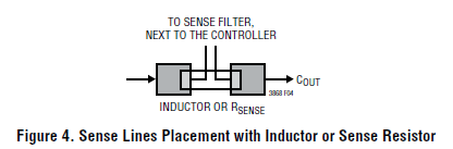
Since you are using the inductor as your sense resistance (inductor “DCR”), you must take your sense traces from right before and after the inductor, and not some distance away from it. Otherwise, you will have a less accurate measurement. You should use a Kelvin connection to sense the voltage across the inductor, as shown in Fig.4 on page 16:
It is not critical to keep the length of gate drive traces equal from the top and bottom MOSFETs, but it can’t hurt. More important is to keep both of their lengths as short as possible to minimize parasitic inductance.
Well noted
Thank you for your time.
