提供:Sparkfun Electronics

SparkFunの提供によります。
ガイド:BBOYHO、ELIAS THE SPARKIEST
はじめに
SparkFunのQwiic dToFイメージャ - TMF8820/TMF8821は、dToF(direct time-of-flight)センサで、AMSの垂直共振器型面発光レーザー(VCSEL)を使用した単一モジュール型パッケージを搭載しています。このdToFデバイスは、単一光子アバランシェフォトダイオード(SPAD)、時間-デジタルコンバータ(TDC)およびヒストグラム技術をベースに、5000mmの検出距離を実現しました。SPADのレンズにより、TMF8820は3x3のマルチゾーン出力データに、またTMF8821は3x3、4x4および3x6のマルチゾーン出力データに対応しています。各dToFイメージャのレンズは、非常に広い視野を提供し、動的に調整することができます。パッケージ内のVCSEL上にあるパッケージ内のマルチレンズアレイ(MLA、Multi-Lens-Array)は、照射角(FoI、Field of Illumination)を拡大します。生データの処理はすべてチップ上で行われ、TMF8820/TMF8821は距離情報を信頼度情報とともにI2Cインターフェースで提供します。オンチップの高性能な光学フィルタが環境光の大部分を遮断するため、暗所でも太陽光の下でも距離計測を可能にします。
カメラのオートフォーカス(Laser Detect Autofocus、LDAF)用距離測定(携帯電話)、存在検知(コンピューティングと通信)、物体検知と衝突回避(ロボット工学)、ライトカーテン(工業)などのプロジェクトに最適なセンサです。
- SparkFun Qwiic dToF Imager - TMF8820
- SparkFun Qwiic Mini dToF Imager - TMF8820
- SparkFun Qwiic dToF Imager - TMF8821
- SparkFun Qwiic Mini dToF Imager - TMF8821

必要な機材
注: プログラムコードを実行するのに十分な容量のフラッシュを搭載したマイコンを推奨します。残念ながら、Arduino Uno(つまりATmega328Pを使用した開発ボード)はご使用になれません。でも、新しいことに挑戦する口実が欲しかったのではありませんか?開発ボードには、Artemis Thing PlusまたはESP32 Thing Plusボードのいずれかをお勧めします。
このチュートリアルに沿って進めるには、以下の機材が必要です。でも、お客様が持っているものによっては、すべてが必要なわけではありません。カートに入れ、ガイドを読み、必要に応じて、カート内の商品を調整してください。なお、以下のWishlistには、RedBoard ArtemisとTMF8821が含まれています。用途に応じて、異なるプロセッサボードやセンサのバージョンなどを選び、カートに入れてください。
Qwiic dToFイメージャTMF8821のWishlist (SparkFunのウィッシュリスト)
- SparkFun Qwiic dToF Imager - TMF8821
- Qwiic Cable - 50mm
- SparkFun RedBoard Artemis
- Reversible USB A to C Cable - 2m
推奨記事
Qwiicシステムに慣れていない場合は、こちらの概要を読むことをお勧めします。
また、以下の技術に慣れていない方は、それぞれのチュートリアルを一度ご覧いただくことをお勧めします。
Logic Levels:3.3Vと5Vのデバイスの違いとロジックレベルについて学びます。
I2C:現在使用されている主要な組込み通信プロトコルの1つであるI2Cの紹介です。
Hookup Guide for the SparkFun RedBoard Artemis:RedBoard Artemis から始めましょう - SparkFun Artemisモジュールの全機能をおなじみのUno R3のフットプリント内に収めています。
Installing Board Definitions in the Arduino IDE:カスタムArduinoボード/コアをインストールするにはどうしたらいいですか?簡単です。このチュートリアルでは、Arduinoボードマネージャを使用してArduinoボード定義をインストールする方法について説明します。また、多くのSparkFun開発ボードに必要なボード定義など、サードパーティのコアを手動でインストールする方法についても説明します。
ハードウェアの概要
まず、今回扱うTMF8820とTMF8821の特性を確認し、どのようなことがボードに期待できるかを知っておきましょう。以下は、データシートから引用した両センサの比較表です。両者はゾーン操作以外はほとんど同じです。通常、各ボードの電源はQwiicコネクタを介して3.3Vで供給されます。

上記2種類のQwiic dToFイメージャは、スタンダードサイズとミニサイズがありますが、同じサイズの場合はともに同じレイアウトです。違いは基板に搭載されているICのみです。基板の上面にあるはんだによるマーキングで見分けることができます。以下は、スタンダードサイズとミニサイズのTMF8820搭載基板のイメージです。


発光部と受光部
TMF8820とTMF8821は、発光部(VCSEL+MLA)と受光部(レンズ+SPAD)で構成されています。発光部は、波長940nmの赤外線レーザーを照射します。スマートフォンのカメラまたはデジタル一眼レフを持ってきて、ボードに電源が入っているときにカメラを斜めに向けてサンプルコードを実行すると、発光部を通してIRを見ることができるはずです。内蔵プロセッサ(ARM M0+ ®)がamsアルゴリズムを実行し、対象物の目標距離を算出します。
注: CLASS 1 レーザー製品、 IEC 60825-1 2014に準拠
TMF8820/8821 ICの発光部(VCSEL+MLA)と受光部(レンズ+SPAD)の向きは、ICの極性マーカーで参照できます。プロジェクトのニーズに合わせて、マーカーに基づいてボードの向きを決める必要があります。下図はTMF8820ですが、3x3 SPAD使用時はTMF8820とTMF8821の両方に適用されます。TMF8820は3×3のSPADにしか対応していません。
以下は、データシートから引用した3x3モードのSPADマップの構成です。なお、データシートでは、強い環境光条件下では、市松模様のSPADマスクを使用することを推奨しています。


TMF8821 ICの発光部(VCSEL+MLA)と受光部(レンズ+SPAD)の向きは、ICの極性マーカーで参照できます。プロジェクトのニーズに合わせて、マーカーに基づいてボードの向きを決める必要があります。下図はTMF8821のもので、4x4と3x6のSPADを使用する場合にのみ適用されます。TMF8821は3x3、4x4あるいは3x6のSPADをサポートします。SPADのサイズを設定するために、必ずICを設定してください。


注: TMF8821を4x4ゾーンで構成して使用する場合、4x4動作モードのゾーンはゾーン1~8および10~17で示され、ゾーン9と18の結果は使用されないので注意してください。このことは、データシートの 「Performance in 4x4 Operating Mode」の項に記載されています。この機能は、TMF8821など一部のバージョンのICにのみ対応しています。
以下は、データシートから引用した4x4モードと3x6モードのSPADマップの構成です。これらの構成はTMF8821で可能です。

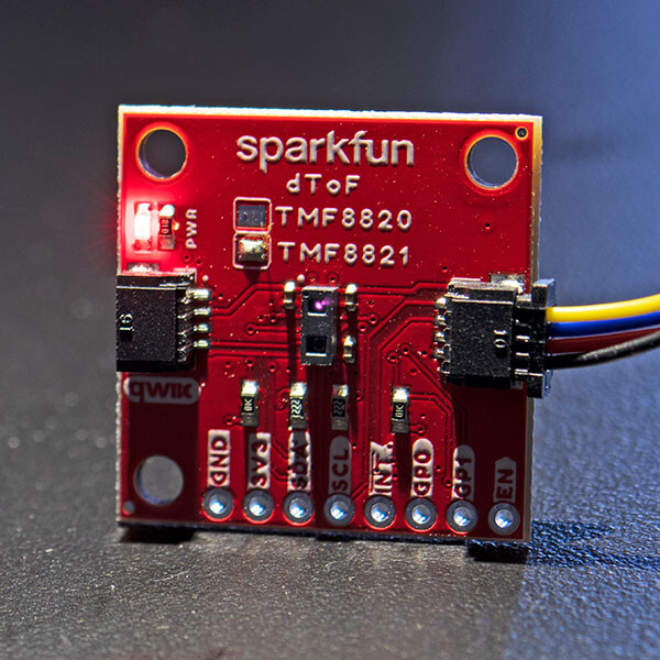
ブレイクアウトピン
ブレイクアウトピンは、以下のようにリストアップされています。Mini版ではピンの配置が変更されていることに注意してください。ほとんどの場合、Qwiicケーブルを使用してセンサにアクセスすることになります。ただし、PTHにヘッダピンやワイヤをはんだ付けする(solder header pins or wires)ことは可能です。


QwiicとI2C
ブレイクアウトボードには2個のQwiicコネクタがあり、I2C データラインおよび電源に簡単にアクセスできます。なお、標準サイズでは、水平嵌合のQwiicコネクタを使用しています。Qwiic ecosystemは、はんだ付けを無くすことで、迅速なプロトタイピングを可能とするように作られています。QwiicコネクタにQwiicケーブルを差し込むだけで、すぐに使えます。各センサのI2Cアドレスは、前述の通り0x41です。


LED
ボードに電源が供給されると、電源LEDが点灯します。無効にするには、基板裏面のトレースをカットしてください。


ジャンパ
基板の裏側には2つのジャンパがあります。ジャンパの変更については、tutorial on working with jumper pads and PCB traces(ジャンパパッドとPCBトレースの加工に関するチュートリアル)をご覧ください。
- I2C - I2Cと書かれたこの3ウエイジャンパは、デフォルトで2つの2.2kΩプルアップ抵抗をI2Cデータ線に接続しています。I2Cデータラインに多くのデバイスがある場合、これらをカットすることを検討してもよいでしょう。
- LED - これはデフォルトで電源LEDに接続されています。LEDを無効にするには、トレースをカットしてください。


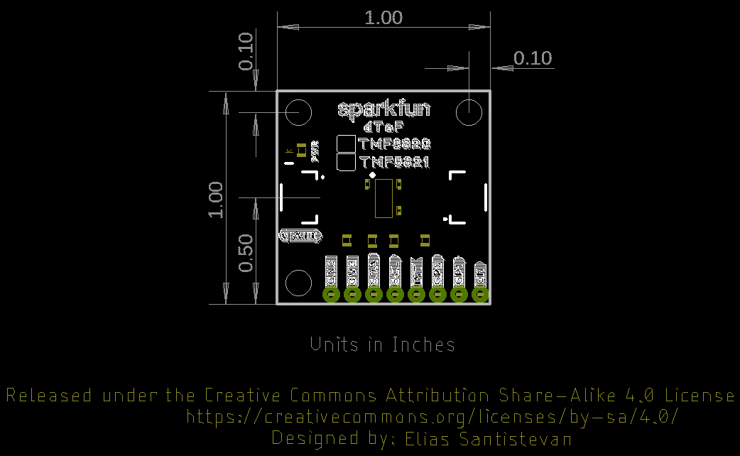
ボードの寸法
Qwiic dToFイメージャTMF8820/TMF8821は、Qwiicの標準サイズ1.0" x 1.0"を使用しています。Miniはフットプリントが半分の0.5" × 1.0"のサイズです。


ハードウェアの接続
注: プログラムコードを実行するのに十分な容量のフラッシュを搭載したマイコンを推奨します。残念ながら、Arduino Uno(つまりATmega328Pを使用した開発ボード)はご使用になれません。でも、新しいことに挑戦する口実が欲しかったのではありませんか?開発ボードには、Artemis Thing PlusまたはESP32 Thing Plusボードのいずれかをお勧めします。
Qwiic dToF TMF8820/TMF8821と互換性のあるArduino互換プロセッサボードは以下の通りです。
- Artemis
- SAMD21/51
- ESP32
- Teensy
- STM32
- nRF52840
Qwiic dToFイメージャを接続するには、Arduino互換の開発ボードとセンサの間にQwiicケーブルを挿入してください。その後、電源とマイコンのプログラミング用のケーブルを挿入します。今回は、RedBoard ArtemisとUSBタイプCケーブルを使用しました。スルーホールピンにハンダ付けするのであれば、電源、グランドおよびI2Cデータラインを、選択しているマイコンに接続すればOKです。TMF8820/TMF8821のSPADとアプリケーションに合わせて、センサの向きを確認してください。今回は、参考までにセンサを反時計回りに90°回転させました。
Qwiic Miniバージョンの場合は、同じ手順でセンサに接続します。違いは基板が小さいことくらいです。下の画像は、RedBoard Artemisとセンサを接続したところです。しかし、より小さなフォームファクタのArduino互換の開発ボードを使用することも可能です。TMF8820/TMF8821のSPADとアプリケーションに合わせて、センサの向きを確認してください。

ソフトウェアのインストール
注: この事例では、デスクトップで最新版のArduino IDEを使用していることを前提にしています。Arduino IDE、ライブラリあるいはボードアドオンを初めてご使用になる場合は、以下のチュートリアルを参照してください。
- Installing the Arduino IDE
- Installing an Arduino Library
- Installing Board Definitions in the Arduino IDE
CH340デバイスを初めてコンピュータに接続する場合、USB-シリアル変換のためのドライバをインストールする必要があります。インストール方法については、「How to Install CH340 Drivers」をご確認ください。
SparkFunのTMF882X dToF Arduinoライブラリは、Arduinoライブラリマネージャで 「SparkFun TMF882X dToF Arduino Library」 を検索してダウンロードできます。または、こちらのGitHub repositoryからzipを取得して手動でインストールすることもできます。
注: APIのリファレンスは、以下のリンクからGitHubのページをご確認ください。
Arduinoの例
以下は、Arduinoのライブラリからピックアップした、いくつかの例を紹介します。
例1:ベーシック
以下の例では、RedBoard Artemisを使用しています。しかし、十分なメモリがあれば、このチュートリアルで先に挙げたArduino互換のマイコンも使うことができます。

ライブラリをインストールしたら、Arduinoでスケッチを開いてみましょう:File > Examples > SparkFun Qwiic TMF882X Arduino Library > Example-01_Basic。 以下のコードは、便宜上、Arduino Libraryからコピーしたものです。コードのアップロードがまだの場合は、ボード(この場合、RedBoard Artemis)および関連するCOMポートを選択します。そしてコードをボードにアップロードします。
/*

  Example-01_Basic.ino

  This demo shows a basic use of a TMF882X device. The device is connected to,
  and a single reading is taken for each loop iteration.

  Supported Boards:

   SparkFun Qwiic dToF Imager - TMF8820        https://www.sparkfun.com/products/19036
   SparkFun Qwiic Mini dToF Imager - TMF8820   https://www.sparkfun.com/products/19218
   SparkFun Qwiic Mini dToF Imager - TMF8821   https://www.sparkfun.com/products/19451
   SparkFun Qwiic dToF Imager - TMF8821        https://www.sparkfun.com/products/19037

  Written by Kirk Benell @ SparkFun Electronics, April 2022

  Repository:
     https://github.com/sparkfun/SparkFun_Qwiic_TMF882X_Arduino_Library

  Documentation:
     https://sparkfun.github.io/SparkFun_Qwiic_TMF882X_Arduino_Library/

  SparkFun code, firmware, and software is released under the MIT License(http://opensource.org/licenses/MIT).
*/

#include "SparkFun_TMF882X_Library.h" //http://librarymanager/All#SparkFun_Qwiic_TMPF882X

SparkFun_TMF882X  myTMF882X;

// Structure to hold the measurement results - this is defined by the TMF882X SDK.

static struct tmf882x_msg_meas_results myResults;

void setup()
{

    delay(1000);
    Serial.begin(115200);
    Serial.println("");

    Serial.println("In setup");
    Serial.println("==============================");

    // Initialize the TMF882X device
    if(!myTMF882X.begin())
    {
        Serial.println("Error - The TMF882X failed to initialize - is the board connected?");
        while(1);
    }else
        Serial.println("TMF882X started.");

    // The device is now ready for operations
}

void loop()
{
    delay(2000);

    // get a Measurement
    if(myTMF882X.startMeasuring(myResults))
    {
        // print out results
        Serial.println("Measurement:");
        Serial.print("     Result Number: "); Serial.print(myResults.result_num);
        Serial.print("  Number of Results: "); Serial.println(myResults.num_results);

        for (int i = 0; i < myResults.num_results; ++i)
        {
            Serial.print("       conf: "); Serial.print(myResults.results[i].confidence);
            Serial.print(" distance mm: "); Serial.print(myResults.results[i].distance_mm);
            Serial.print(" channel: "); Serial.print(myResults.results[i].channel);
            Serial.print(" sub_capture: "); Serial.println(myResults.results[i].sub_capture);

        }
        Serial.print("     photon: "); Serial.print(myResults.photon_count);
        Serial.print(" ref photon: "); Serial.print(myResults.ref_photon_count);
        Serial.print(" ALS: "); Serial.println(myResults.ambient_light); Serial.println();

    }

}
Arduino Serial Monitor を開いて、115200ボーに設定してください。dToFイメージャのICの前に、指または平らで硬い物体などを置きます。以下の出力と同じようなものが表示されるはずです。読み取り値は、信頼度値[信頼度値は0から255の間で、255が最高値]と、各チャネル[.channel]のミリメートル単位の距離測定値 [.distance_mm]を示しています。出力は、受信した合計フォトン[.photon_count]、参照フォトン[.ref_photon_count]およびチャンネルによって受信されたチュートリアル環境光[.ambient_light]に関する情報も提供します。
チャンネル1~3を覆い、TMF8820/TMF8821に近づけるように対象物を配置してみてください。今回は、厚紙でセンサを部分的に覆っています。出力の変化を見やすくするために、下の画像のようにSPADに対するボードの向きを確認してください。

シリアルモニタを開いたままにしておくと、以下のような出力が表示されるはずです。センサがチャンネル1~3にわたって高い信頼度で物体を検出できたことがわかります。段ボールで覆われていない他のチャンネルの値は、信頼度が低く、距離の長い値を示しており、私の机の上から天井までの距離(つまり12フィート)に近い値になっています。TMF8820/TMF8821は、SPADが反射パルスを受信しない場合、結果を表示しないことがあります。

例5:詳細
ライブラリがインストールされた状態で、Arduinoでスケッチを開いてみましょう:File > Examples > SparkFun Qwiic TMF882X Arduino Library > Example-05_Verbose。以下のコードは、便宜上、Arduino Libraryからコピーしたものです。コードのアップロードがまだの場合は、ボード(この場合、RedBoard Artemis)および関連するCOMポートを選択します。そしてコードをボードにアップロードします。
/*

  Example-05_Verbose.ino

  The TMF882X Arduino library uses the TMF882X Software Development Kit (SDK) from
  AMS to interface with the sensor.

  The AMS SDK is able to print out informational messages during normal operation, as
  well as debug messages. This example shows how to enable those messages and direct
  them to a Serial device for output.

  Supported Boards:

   SparkFun Qwiic dToF Imager - TMF8820        https://www.sparkfun.com/products/19036
   SparkFun Qwiic Mini dToF Imager - TMF8820   https://www.sparkfun.com/products/19218
   SparkFun Qwiic Mini dToF Imager - TMF8821   https://www.sparkfun.com/products/19451
   SparkFun Qwiic dToF Imager - TMF8821        https://www.sparkfun.com/products/19037

  Written by Kirk Benell @ SparkFun Electronics, April 2022

  Repository:
     https://github.com/sparkfun/SparkFun_Qwiic_TMF882X_Arduino_Library

  Documentation:
     https://sparkfun.github.io/SparkFun_Qwiic_TMF882X_Arduino_Library/

  SparkFun code, firmware, and software is released under the MIT License(http://opensource.org/licenses/MIT).
*/

#include "SparkFun_TMF882X_Library.h"    //http://librarymanager/All#SparkFun_Qwiic_TMPF882X

SparkFun_TMF882X  myTMF882X;

static struct tmf882x_msg_meas_results myResults;

void setup()
{

    delay(1000);
    Serial.begin(115200);
    Serial.println("");

    Serial.println("In setup");
    Serial.println("==============================");

    // The underlying TMF882X SDK can output a wide variety of information during
    // normal operation. It's very verbose.
    //
    // Enable this output as part of this demo.
    //
    // Pass in our output device - Serial

    myTMF882X.setOutputDevice(Serial);

    // Enable Info messages
    myTMF882X.setInfoMessages(true);

    // Enable Debug mode. Set this before calling begin to get initialization debug
    // information.

    myTMF882X.setDebug(true);

    if(!myTMF882X.begin())
    {
        Serial.println("Error - The TMF882X failed to initialize - is the board connected?");
        while(1);
    }else
        Serial.println("TMF882X started.");


}

void loop()
{
    delay(2000);

    // get a myResultsurment
    if(myTMF882X.startMeasuring(myResults))
    {
        // print out results
        Serial.println("Measurement:");
        Serial.print("     Result Number: "); Serial.print(myResults.result_num);
        Serial.print("  Number of Results: "); Serial.println(myResults.num_results);

        for (uint32_t i = 0; i < myResults.num_results; ++i)
        {
            Serial.print("       conf: "); Serial.print(myResults.results[i].confidence);
            Serial.print(" distance mm: "); Serial.print(myResults.results[i].distance_mm);
            Serial.print(" channel: "); Serial.print(myResults.results[i].channel);
            Serial.print(" sub_capture: "); Serial.println(myResults.results[i].sub_capture);

        }
        Serial.print("     photon: "); Serial.print(myResults.photon_count);
        Serial.print(" ref photon: "); Serial.print(myResults.ref_photon_count);
        Serial.print(" ALS: "); Serial.println(myResults.ambient_light); Serial.println();

    }

}
Arduino Serial Monitorを開いて、115200ボーに設定してください。出力は、「べーシック」の例と同様です。ただし、追加で表示される情報があります。この情報は、TMF8820やTMF8821でデバッグをする際に役立ちます。測定は、物体がICを完全に覆っている状態で行いました。

例8:工場出荷時の校正
この例は、TMF8820やTMF8821を最終的に実装し、SPADマスクの選択を調整する際にお勧めします。データシートの7.3 Calibrationにあるように、 校正は、周囲光が少なく、TMF8820/21の視野の40cm以内に対象物がないハウジング内で行うこと」と提案されています。
ライブラリがインストールされた状態で、Arduinoでスケッチを開いてみましょう:File > Examples > SparkFun Qwiic TMF882X Arduino Library > Example-08_FactoryCal。以下のコードは、便宜上、Arduino Libraryからコピーしたものです。コードのアップロードがまだの場合は、ボード(この場合、 RedBoard Artemis)および関連するCOMポートを選択します。そしてコードをボードにアップロードします。
/*

  Example-08_FactoryCal.ino

  This example shows how to peform a Factory Calibration on the connected
  TMF882X device. Details on the calibration and it's use are contained in
  the TMF882X datasheet.

  Supported Boards:

   SparkFun Qwiic dToF Imager - TMF8820        https://www.sparkfun.com/products/19036
   SparkFun Qwiic Mini dToF Imager - TMF8820   https://www.sparkfun.com/products/19218
   SparkFun Qwiic Mini dToF Imager - TMF8821   https://www.sparkfun.com/products/19451
   SparkFun Qwiic dToF Imager - TMF8821        https://www.sparkfun.com/products/19037

  Written by Kirk Benell @ SparkFun Electronics, April 2022

  Repository:
     https://github.com/sparkfun/SparkFun_Qwiic_TMF882X_Arduino_Library

  Documentation:
     https://sparkfun.github.io/SparkFun_Qwiic_TMF882X_Arduino_Library/

  SparkFun code, firmware, and software is released under the MIT License(http://opensource.org/licenses/MIT).
*/


#include <SparkFun_TMF882X_Library.h>    //http://librarymanager/All#SparkFun_Qwiic_TMPF882X

SparkFun_TMF882X  myTMF882X;

void setup()
{

    delay(1000);
    Serial.begin(115200);
    Serial.println("");

    Serial.println("In setup");
    Serial.println("==============================");

    if(!myTMF882X.begin())
    {
        Serial.println("Error - The TMF882X failed to initialize - is the board connected?");
        while(1){}
    }else
        Serial.println("TMF882X started.");


    Serial.println();
    Serial.println("Performing a Factory Calibration.");
    Serial.println();
    // Perform a factory calibration of the connected device.

    // First set some config parameters to support the calibration
    struct tmf882x_mode_app_config tofConfig;
    if (!myTMF882X.getTMF882XConfig(tofConfig))
    {
        Serial.println("Error - unable to get device configuration.");
        while(1){}
    }

    // Change the APP configuration
    //  - set the reporting period to 500 milliseconds
    //  - set the iterations to 4,000,000 (4M) to perform factory calibration
    tofConfig.report_period_ms = 500;
    tofConfig.kilo_iterations = 4000;

    if (!myTMF882X.setTMF882XConfig(tofConfig))
    {
        Serial.println("Error - unable to set device configuration.");
        while(1){}
    }

    struct tmf882x_mode_app_calib factoryCal;

    // Peform the calibration
    if (!myTMF882X.factoryCalibration(factoryCal))
    {
        Serial.println("Error - Factory Calibration Failed.");
        while(1){}
    }

    // Output the calibration
    Serial.println("Calibration Complete");
    Serial.println();
    Serial.print("Calibration Data Length: ");
    Serial.println(factoryCal.calib_len);

    Serial.println("Calibration Data:");
    for (int i = 0; i < factoryCal.calib_len; i++)
    {
        Serial.print("   "); Serial.print(factoryCal.data[i]);

        if ( (i + 1) % 16 == 0 )
            Serial.println();
    }
    Serial.println();

}

void loop()
{
    delay(2000);

    // Nothing - just here for the calibration example
}
Arduino Serial Monitorを開いて、115200ボーに設定してください。下の画像のような出力が表示されます。データシートに従って、センサを正しく校正してください。

例9:SPADマップ
注: TMF8820/TMF8821の電源を入れるたびにSPADの設定(たとえば、SPAD_MAP_ID)をロードする必要があります。また、SPADマップを調整した後は、必ずセンサのキャリブレーションを行ってください。
ライブラリがインストールされた状態で、Arduinoでスケッチを開いてみましょう:File > Examples > SparkFun Qwiic TMF882X Arduino Library > Example-09_SPADMap。以下のコードは、便宜上、Arduino Libraryからコピーしたものです。コードのアップロードがまだの場合は、ボード(この場合、RedBoard Artemis)および関連するCOMポートを選択します。そしてコードをボードにアップロードします。
/*

  Example-09_SPADMap.ino

  The Optical performance of the TMF882X is controled by a SPAD (Single Photon
  Avalanche Photodiode) Map.

  SPAD Maps are set using a SPAD Map ID, which are detailed in the TMF882X datasheet.

  This example shows how to determine the current SPAD Map on the device and change
  it to a desired map.

  Supported Boards:

   SparkFun Qwiic dToF Imager - TMF8820        https://www.sparkfun.com/products/19036
   SparkFun Qwiic Mini dToF Imager - TMF8820   https://www.sparkfun.com/products/19218
   SparkFun Qwiic Mini dToF Imager - TMF8821   https://www.sparkfun.com/products/19451
   SparkFun Qwiic dToF Imager - TMF8821        https://www.sparkfun.com/products/19037

  Written by Kirk Benell @ SparkFun Electronics, April 2022

  Repository:
     https://github.com/sparkfun/SparkFun_Qwiic_TMF882X_Arduino_Library

  Documentation:
     https://sparkfun.github.io/SparkFun_Qwiic_TMF882X_Arduino_Library/

  SparkFun code, firmware, and software is released under the MIT License(http://opensource.org/licenses/MIT).
*/

#include <SparkFun_TMF882X_Library.h>    //http://librarymanager/All#SparkFun_Qwiic_TMPF882X

static struct tmf882x_msg_meas_results myResults;


SparkFun_TMF882X  myTMF882X;

// What SPAD map to change to

#define NEW_SPAD_MAP 2

void setup()
{

    delay(1000);
    Serial.begin(115200);
    Serial.println("");

    Serial.println("In setup");
    Serial.println("==============================");

    if(!myTMF882X.begin())
    {
        Serial.println("Error - The TMF882X failed to initialize - is the board connected?");
        while(1){}
    }else
        Serial.println("TMF882X started.");


    // Let's change the SPAD map in use on this device.
    //
    // Get the current SPAD Map ID
    int spadMap =  myTMF882X.getCurrentSPADMap();
    Serial.println();
    Serial.print("Current SPAD Map ID: ");
    Serial.println(spadMap);

    // Now switch
    Serial.println("Switching SPAD Map to ID 2 - 3x3 Macro 1 off center");
    Serial.println();

    if (!myTMF882X.setCurrentSPADMap(NEW_SPAD_MAP))
    {
        Serial.println("Error -  Failed to set the SPAD Map - halting");
        while(1){}
    }

    // Let's make sure it worked
    spadMap =  myTMF882X.getCurrentSPADMap();

    if(spadMap != NEW_SPAD_MAP)
    {
        Serial.println("Error -  Failed to set the SPAD Map - halting");
        while(1){}
    }

    Serial.print("The new SPAD Map ID: ");
    Serial.println(spadMap);

    // Now set some config parameters to support the spad map
    struct tmf882x_mode_app_config tofConfig;

    if (!myTMF882X.getTMF882XConfig(tofConfig))
    {
        Serial.println("Error - unable to get device configuration.");
        while(1){}
    }

    // Change the APP configuration
    //  - set the reporting period to 500 milliseconds
    tofConfig.report_period_ms = 500;

    if (!myTMF882X.setTMF882XConfig(tofConfig))
    {
        Serial.println("Error - unable to set device configuration.");
        while(1){}
    }

}

void loop()
{
    delay(2000);

    // get a myResultsurment
    if(myTMF882X.startMeasuring(myResults))
    {
        // print out results
        Serial.println("Measurement:");
        Serial.print("     Result Number: "); Serial.print(myResults.result_num);
        Serial.print("  Number of Results: "); Serial.println(myResults.num_results);

        for (int i = 0; i < myResults.num_results; ++i)
        {
            Serial.print("       conf: "); Serial.print(myResults.results[i].confidence);
            Serial.print(" distance mm: "); Serial.print(myResults.results[i].distance_mm);
            Serial.print(" channel: "); Serial.print(myResults.results[i].channel);
            Serial.print(" sub_capture: "); Serial.println(myResults.results[i].sub_capture);

        }
        Serial.print("     photon: "); Serial.print(myResults.photon_count);
        Serial.print(" ref photon: "); Serial.print(myResults.ref_photon_count);
        Serial.print(" ALS: "); Serial.println(myResults.ambient_light); Serial.println();

    }
}
この例では、SPAD の動作モードを選択することができます。データシートの「8.5.17 SPAD_MAP_ID Register」に許容値およびモードのリストがあります。ただし、一部の値は予約されており、TMF8820(例:3x3に限定)またはTMF8821(例:3x3、4x4、3x6に限定)では使用できないゾーン構成があります。
アップロードしたら、Arduino Serial Monitorを115200ボーで開き、チャンネル1~3を覆います。spad_map_idを2に変更しました。SPADがデフォルトの3x3ノーマルモードを使用した場合、例1と同様の測定値になります。しかし、SPADは異なるFOVを使用しますので、わずかにオフセットしています。

TMF8821の場合、spad_map_idを7に変更することでSPADを41° x 52°FoVの4x4ノーマルモードに調整してみてください(つまり、#define NEW_SPAD_MAP 2の行を#define NEW_SPAD_MAP 7に変更します)。そして、そのコードをボードにアップロードしてください。
Arduino Serial Monitorを115200ボーで開き、チャンネル9から16を覆ってみてください。下の画像のような出力が表示され、それぞれのチャンネルが覆われたことがわかります。

注: :カスタムSPADマップについては、Example-10_CustomSPADMapおよび関連するヘッダファイルをチェックして、あなた自身のカスタムSPAD設定を定義してみてください。
例11:ヒストグラム
ライブラリがインストールされた状態で、Arduinoでスケッチを開いてみましょう: File > Examples > SparkFun Qwiic TMF882X Arduino Library > Example-11_Histogram。以下のコードは、便宜上、Arduino Libraryからコピーしたものです。コードのアップロードがまだの場合は、ボード(この場合、RedBoard Artemis)および関連するCOMポートを選択します。そしてコードをボードにアップロードします。
/*

  Example-11_Histogram.ino

  This example shows how to enable and recieve raw histogram data from the
  connected TMF882X device

  Supported Boards:

   SparkFun Qwiic dToF Imager - TMF8820        https://www.sparkfun.com/products/19036
   SparkFun Qwiic Mini dToF Imager - TMF8820   https://www.sparkfun.com/products/19218
   SparkFun Qwiic Mini dToF Imager - TMF8821   https://www.sparkfun.com/products/19451
   SparkFun Qwiic dToF Imager - TMF8821        https://www.sparkfun.com/products/19037

  Written by Kirk Benell @ SparkFun Electronics, April 2022

  Repository:
     https://github.com/sparkfun/SparkFun_Qwiic_TMF882X_Arduino_Library

  Documentation:
     https://sparkfun.github.io/SparkFun_Qwiic_TMF882X_Arduino_Library/

  SparkFun code, firmware, and software is released under the MIT License(http://opensource.org/licenses/MIT).
*/

#include "SparkFun_TMF882X_Library.h"  //http://librarymanager/All#SparkFun_Qwiic_TMPF882X

SparkFun_TMF882X  myTMF882X;

#define NUMBER_OF_SAMPLES_TO_TAKE  4

int nSample = 0;

// For our histogram printout
#define MAX_BIN_LEN 128

// Define our histogram callback function

void onHistogramCallback(struct tmf882x_msg_histogram *myHistogram)
{

    nSample++;

    Serial.print("Histogram Number: ");
    Serial.println(nSample);

    uint8_t zone_count = 0;
    for (int tdc_idx = 0; tdc_idx < myHistogram->num_tdc; ++tdc_idx)
    {
        // Histogram tag for zones, #HLONG01,#HLONG02....
        Serial.println();
        Serial.print("#HLONG");
        Serial.print(zone_count++);

        for (int bin_idx = 0; bin_idx < myHistogram->num_bins; ++bin_idx) {

            Serial.print((unsigned long)myHistogram->bins[tdc_idx][bin_idx]);

            if ((bin_idx + 1) == MAX_BIN_LEN)
            {
                Serial.println();
                Serial.print("#HLONG");
                Serial.print(zone_count++);

            } else if ((bin_idx + 1) % MAX_BIN_LEN != 0)
                Serial.print(",");
        }
    }
    Serial.println();
}

void setup()
{

    delay(500);
    Serial.begin(115200);
    Serial.println("");


    if(!myTMF882X.begin())
    {
        Serial.println("Error - The TMF882X failed to initialize - is the board connected?");
        while(1){}
    }

    // set our call back function that handles histograms
    myTMF882X.setHistogramHandler(onHistogramCallback);

    // Set our delay between samples  - 1 second - note it's in ms
    myTMF882X.setSampleDelay(1000);

    // First config parameter to enable output of histogram data.

    struct tmf882x_mode_app_config tofConfig;
    if (!myTMF882X.getTMF882XConfig(tofConfig))
    {
        Serial.println("Error - unable to get device configuration.");
        while(1){}
    }

    // Change the APP configuration
    //  - set the reporting period to 500 milliseconds
    //  - Enable Histogram mode
    tofConfig.report_period_ms = 500;
    tofConfig.histogram_dump = 1;

    if (!myTMF882X.setTMF882XConfig(tofConfig))
    {
        Serial.println("Error - unable to set device configuration.");
        while(1){}
    }
}

void loop()
{
    delay(2000);

    // get a measurment
    // Have the sensor take 4 measurements, the results are sent to the above callback

    Serial.println("---------------------------------------------------------");
    Serial.print("Taking ");
    Serial.print(NUMBER_OF_SAMPLES_TO_TAKE);
    Serial.println(" data samples.");
    Serial.println();

    nSample=0;
    myTMF882X.startMeasuring(NUMBER_OF_SAMPLES_TO_TAKE);

    Serial.println("---------------------------------------------------------\n\n");

}
Arduino Serial Monitorを115200ボーで開き、TMF8820とTMF8821の生のヒストグラムデータを表示させます。このサンプルコードでは、現在一度に4つのデータサンプルを取得するように設定されていることに注意してください。センサを覆っている場合は、以下の画像のような出力が表示されるはずです。

もっと例があります!
このチュートリアルでは、Arduinoライブラリに掲載されているいくつかの例を取り上げて、使い方を説明しています。他の例もライブラリに掲載されています。
トラブルシューティング
期待通りに動作せず、お困りですか?
期待通りの動作をしない製品について技術的なサポートや詳細情報が必要な場合は、SparkFun Technical Assistanceページにアクセスし、初期のトラブルシューティングを行うことをお勧めします。
必要なものが見つからない場合は、SparkFun Forumsでヘルプを検索し、質問することができます。初めてご利用になる場合は、フォーラムアカウントを作成し、製品フォーラムを検索して質問を投稿してください。
リソース、そしてとさらに上を目指すために
Qwiic dToFイメージャを無事に起動させたら、次はそれをご自分のプロジェクトに組み込んでみましょう。より詳しい情報は、以下の資料をご覧ください。
- SparkFun Qwiic dToFイメージャ - TMF8820
- SparkFun Qwiic Mini dToFイメージャ- TMF8820
- SparkFun Qwiic dToFイメージャ - TMF8821
- SparkFun Qwiic Mini dToFイメージャ - TMF8821
- TMF882X
- Arduino Library
- GitHub Hardware Repo
- SFE Product Showcase
主要部品・コンポーネント


- 1568-SEN-19036-ND
- 1568-SEN-19218-ND
- 1568-SEN-19037-ND
- 1568-SEN-19451-ND
- 1568-WRL-15574-ND
- 1568-WRL-15663-ND
- 1568-PRT-17260-ND
- 1568-DEV-15444-ND
- 1568-CAB-15424-ND