The general advantages of thermistors used as temperature sensors are a relatively low cost, potential for good accuracy, and availability in packages that can be quite small. Typical disadvantages include a highly non-linear temperature response and a limited range of operating temperatures compared to other sensing technologies.
PTC Thermistors
Devices that can be fairly called PTC thermistors vary widely in their composition and behavior, making classification and characterization of these devices somewhat complex. Devices in the PTC Thermistor temperature sensor family are more often optimized for and characterized in terms of their use in temperature measurement or temperature detection applications, whereas those in the PTC Resettable Fuse family tend to be characterized for use as a circuit protection device. Some overlap however, does occur.
Product Attributes
Beyond the routine matters of manufacturer, packaging, and physical form, four product attributes were available for aiding selection of a PTC thermistor at the time of writing and are described below.
Resistance @ 25°C
This parameter describes the nominal resistance of a product when measured at a device temperature of 25°C. It is not an exact value, but will vary among examples of any particular part number to an extent characterized by the Resistance Tolerance parameter.
Resistance Tolerance
This parameter describes variability of the Resistance @ 25°C parameter between individual examples of the same part number, due to manufacturing variation.
Operating Temperature
The specific meaning of this product attribute is subject to variation, depending on the intended use for a given device. Typically, it reflects the range of device temperature over which a device is characterized for operation by the manufacturer; operation outside this range may result in degraded device performance or permanent changes to device characteristics. Such characterizations typically indicate a wide temperature range of the sort over which electronic components of other types are commonly characterized, e.g. -40~80°C.
Alternatively, this attribute may be used to communicate an expected operating point, an ambient temperature range within which a device is recommended for use, or something different. Such characterizations typically indicate narrower temperature ranges near or above common ambient temperatures, e.g. +10~55°C. Such alternative meanings are typically associated with devices intended for use as temperature-based switches.
Power- Max
At the time of writing, the information reflected by this parameter was rather incomplete with data available for approximately 25% of listed products. Variability was also in evidence with regard to its specific meaning as a result of differences in products’ intended function; for some products it characterizes the amount of power dissipation that would cause the device’s internal temperature to reach its rated maximum under some specified ambient temperature and mounting conditions. For others, it characterizes the typical amount of power that a product would dissipate under specified operating conditions.
Common Applications
Temperature Measurement
PTC Thermistor products optimized for temperature measurement applications are available, which offer the convenience of a positive temperature correlation and greater linearity than available from typical NTC thermistor sensors. While the measurement accuracy and temperature sensitivity achievable using such products tends to be less, for some applications it is sufficient while offering a simpler means of application that recommends their use. The TFPT0603L1000JV is an example of one such device, datasheet excerpts for which are shown in figures 1 and 2.

Figure 1. Excerpt from TFPT0603L1000JV datasheet, showing variation in device resistance as a function of temperature. Note the nearly linear nature of this characteristic over a wide temperature range.

Figure 2. Characteristic data for the device of figure 1. Note that the TCR (Temperature Coefficient of Resistance) tolerance is approximately ±10% of the nominal value, even among products for which the resistance tolerance is held to within ±0.5%
Temperature Detection
Another common application for PTC thermistors might be better described as temperature detection , rather than temperature measurement . The distinguishing trait of these devices is a temperature behavior that is not linear, but which increases precipitously beyond some specified approximate temperature. Devices of this type are typically used to monitor for over-temperature conditions, where precise temperature measurements are not so much a concern as detecting when temperatures are in excess of some general “safe” value. An example of such a device would be P/N B59421A0075A062, for which a relevant datasheet excerpt is shown as figure 3. While the nominal resistance of this device is 470 ohms @ 25°C, the tolerance on this figure is a very generous ±50%. From -40 to approximately 50°C, the resistance of these parts can be expected to linger between roughly 400 and 700 ohms, and in fact may actually increase as temperature decreases, contrary to what its being called a PTC thermistor might imply. Beyond about 70°C however, the parts’ resistance increases unambiguously above about 1.5K, reaching 5K by the time temperature increases to 80°C, and 10K by 90°C. This behavior allows realization of simple, small, low-cost detection of temperatures that are typically problematic for electronic systems.

Figure 3. B59421A0075A062 datasheet excerpt illustrating typical device characteristics and tolerance band. Note the logarithmic scale used for resistance values.
Circuit Protection
PTC thermistors used for temperature detection are typically operated with very low current flows in order to minimize self-heating of the sensor, with the signal produced causing some other device to take protective action. In other circumstances, most or all of the power supply current for a circuit may be passed through a PTC thermistor with a similarly abrupt characteristic, in order to provide protection against excess temperature and short circuit/overload faults. While the majority of such devices are classified as PTC resettable fuses, some end up also being classified as PTC thermistors. These products tend to be physically larger and have relatively low nominal ohmic values, with the B59840C0160A070 (called a C840 type by the manufacturer) being an example. Datasheet excerpts for this product are shown in figures 4-6.

Figure 4. B59840C0160A070 datasheet excerpt showing device dimensions for this and similar products in the device series.

Figure 5. Datasheet excerpt showing electrical operating characteristics for C840 series devices and related products. The C840 type mentioned would be used to protect circuits normally drawing 400mA or less, would be expected to transition to a high-resistance state as current flow exceeds about 800mA, should not be called upon to interrupt current flows greater than 4.1A, permits a residual current of about 18mA to flow when in a high-resistance state with maximum rated voltage applied, has a nominal 25°C resistance of approximately 6 ohms, 3.6 ohms minimum.
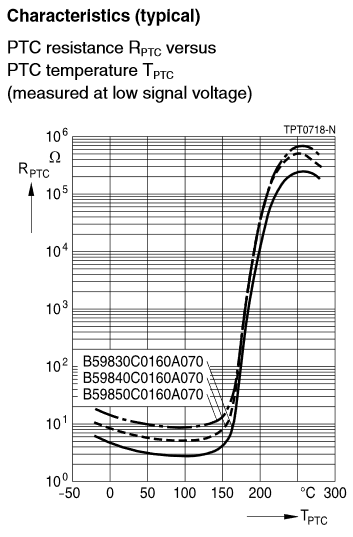
Figure 6. Datasheet excerpt showing relationship between temperature and device resistance. When operating in a protective mode with rated voltage applied, device temperatures would be expected to rise to somewhere between 150° and 200°C.
Heating
PTC thermistors can function as a convenient, self-regulating heat source capable of maintaining a reasonably stable temperature despite significant variations in supply voltage and thermal load. Devices used in this way are of the type having an abrupt increase in resistance beyond a certain temperature, and are commonly sold as metallized discs or rectangles designed to be mounted by clamping between two electrical contacts in a manner that accommodates the thermal expansion expected from such use. The B59060A0060A010 is an example of such a device, pictured in figure 7 with a datasheet excerpt shown as figure 8. The rapid increase in device resistance with temperature beyond a certain point results in a temperature-limiting behavior; the example device with 12V applied could be expected to maintain a temperature of roughly 60 to 90°C depending on thermal conditions.

Figure 7.

Figure 8.
NTC Thermistors
Product Attributes
Beyond the routine attributes describing manufacturer, packaging, and physical form, a number of parameters describing characteristics of NTC thermistor products are available to aid product selection, and are described below.
Resistance @ 25°C
This parameter describes the nominal resistance of a product when measured at a device temperature of 25°C. Actual values will vary among examples of devices of the same part number due to manufacturing variation, to an extent characterized by the Resistance Tolerance Parameter.
Resistance Tolerance
This parameter describes the extent to which an individual device’s resistance at a 25°C temperature may vary from stated nominal values at the time of delivery, typically in terms of a percentage of nominal resistance value. For devices characterized over some specified temperature range rather than at a single temperature, a tolerance value may also be shown here using units of temperature. Further information on this topic can be found under the heading Manufacturing Tolerances.
B#/#
Listings for various B (or ß, Greek letter beta) values characterize a thermistor’s resistance vs. temperature curve, based on actual device measurements at two indicated temperature points. For example, B0/50 values indicate a beta value derived from measurements of device resistance at 0°C and 50°C. Because the equation used to derive B values does not perfectly represent the underlying device behavior, models of device R vs T curves based on use of B values are less precise than other methods, and the resulting B values are dependent on the temperature measurement points chosen. Further discussion on these issues can be found under the Manufacturing Tolerances heading.
B Value Tolerance
This attribute describes the extent to which actual B (beta) values exhibited by a given product may deviate from listed nominal values as a result of manufacturing variability, when measured under specified test conditions.
Operating Temperature
This parameter describes the temperature range over which a device is characterized for operation by the manufacturer. Operation outside these limits may result in diminished device performance, permanent alteration of device characteristics, or physical damage.
Power- Max
At the time of writing, the information reflected by this parameter was somewhat incomplete with data available for slightly more than half of listed products. It typically characterizes the maximum amount of power that may be dissipated in a device on a continuous basis, under manufacturer-defined test conditions including ambient temperature and mounting. It is commonly (though not exclusively) reckoned as the amount of power that will cause a device to reach its maximum rated internal operating temperature under these conditions.
Resistance vs. Temperature
The relationship between resistance and temperature for an NTC thermistor is distinctly non-linear, complicating the task of interpreting resistance measurements in terms of temperature. Two mathematical models are commonly used for this task.
The first and simpler of these describes a thermistor curve in terms of a single variable, ß (Greek letter beta, commonly written as B for convenience) derived by measuring thermistor resistance at two different temperatures and calculated according to the equation below where Rx is the thermistor resistance at an absolute temperature of Tx.

Rearranging to solve for temperature or resistance given a beta value and resistance at a reference temperature, the equation becomes:

Plots of normalized R vs T curves for various beta values are shown in figure 9. It can be seen that higher values of beta correspond to a more dramatic change in device resistance for a given change in temperature.

Figure 9. Normalized resistance vs temperature for varying values of beta.
This model is commonly used over relatively narrow temperature ranges and/or where relatively large errors are tolerable; the equation does not represent the underlying device behaviors well over a wide range of conditions. An indication of this can be seen by noting that the selection of temperatures used for calculating beta values has a subtle, but noticeable influence on the resulting value. Using tabulated data provided in the datasheet for the NTCLE100E3338JB0 as an example, resulting beta values calculated using different temperature points are as follows:
| Temperature Points | Beta Value |
|---|---|
| B0/50 | 2858 |
| B25/50 | 2873 |
| B25/75 | 2878 |
| B25/85 | 2880 |
| B25/100 | 2882 |
Using the tabulated data as a reference, the error expected from use of these different beta values is shown in figure 10 as a function of temperature, along with another model to be discussed shortly. Some clearly do better than others though as temperatures fall below about 0°C, none of the beta values serve well.

Figure 10. Plot of temperature error vs. temperature when using beta values calculated at different temperatures, and expanded Steinhart-Hart equation using coefficients given in device datasheet.
The second model commonly used for relating thermistor resistance to temperature is known as the Steinhart-Hart equation, and is used over broader temperature ranges and/or where smaller errors are desired. In its common form, it uses 3 constants to characterize a thermistor temperature curve, according to the equation:
![]()
Where T is absolute temperature, R is thermistor resistance at temperature T, and A, B, and C are constants. These constants may be determined by making careful measurements of device resistance at 3 equally-spaced temperatures spanning the range of interest, and solving the resulting system of three equations for the three unknowns A, B, and C. Though popular and in common use since its introduction in the 1960s, greater fidelity of result can be had through the use of a more thorough expansion of the underlying mathematical series:

Here, R, T, A, B etc. have the same meanings as before, with the additional R0 term having a meaning that is somewhat dependent on who one asks. The original Steinhart-Hart equation presumes it to be one, some sources describe it as device resistance at a temperature of 25°C, while others describe it as a reference resistance of some other value. Practically speaking, the issue is perhaps most important when using pre-calculated values for the constants A, B, etc. since significant errors occur if a consistent interpretation of R0 is not maintained. An example of this might be attempting to calculate temperature using resistance values measured in kΩ using constants derived using measurements in ohms.
Models of this kind (possibly including a fourth or even fifth-order term)) have been found sufficient to allow modeling of thermistor curves to a degree of accuracy comparable to the remaining uncertainties in the empirical measurements. Effects of a more subtle character regarding the interpretation of R0 in these contexts have been reported; those interested in splitting a °C into many pieces are advised to study the matter more closely.
Finally, a less computational approach to dealing with thermistor non-linearity is the distribution of tabulated resistance and temperature values across a device’s operating temperature range, allowing a simple table lookup operation to relate resistance and temperature values for a given device. Particularly for low-end microcontroller applications where memory space is more available than computational power, this approach has much to recommend it.
Thermistor Resistance Measurement
Techniques used for interrogating an NTC thermistor used as a temperature sensor are numerous and varied. The arrangement shown in figure 11 however stands out due to its simplicity, low cost, and convenience for use with common microcontrollers, and as such will receive brief mention here.

Figure 11.
By connecting the NTC thermistor to be queried in series with a fixed resistor of known value (R) in this way, the signal Vout increases with temperature and is proportional to the excitation voltage VRef provided. This arrangement is extremely convenient for use with common analog-digital converters (ADCs) which generate a digital output code representing the magnitude of an analog input compared to some reference value.
Neglecting contributions from self-heating, ADC error terms and the like, figure 12 shows the expected output code from a 10-bit ADC as a function of temperature for different values of series resistance.

Figure 12. Output code of a 10-bit ADC vs temperature for thermistor P/N NTCLE100E3103GB0 with varying values of series resistance.
In each case, within roughly ±20°C of the point where the thermistor resistance equals that of the series resistor the output code is a reasonably linear and sensitive function of temperature, changing by about 10 codes per °C. Sensitivity degrades with distance from that mid-scale point, to an extent where a difference of one ADC code can represent a change in temperature of perhaps 10°C.
By choosing an appropriate series resistor, the figure 11 circuit can be sufficient to enable measurement with 0.5°C resolution over a 40°C span using the 10-bit converters common among contemporary microcontrollers. Use of higher-resolution converters can of course improve these figures.
Thermistor Self-Heating
The typical means of measuring the resistance of a device such as a thermistor is to apply a known voltage across it and measure the current flow that results. Alternatively, one might pass a known current through and measure the resulting voltage. Either approach or something in between results in electrical power dissipation in the thermistor (called “self heating”) causing its temperature to increase above that of its surroundings and disturbing the attempt to measure the temperature of those surroundings. The degree to which such power dissipation affects thermistor temperature is often described as a “dissipation factor” and is commonly quoted in terms of power per temperature, e.g. 5mW/°C. Such a value would indicate that the device temperature (under specified test conditions) would increase by 1°C for every 5mW of electrical power dissipated in the device. If a 1 mA current were used to query such a thermistor having a resistance of 1K, the resulting error due to self-heating would be approximately 0.2°C:
![]()

It is important to note that the effect of self-heating tends to introduce errors that vary systematically with temperature. This same 1K thermistor may exhibit a resistance closer to 3.3kΩ at 0°C and 360Ω at 50°C, in which case the error due to self-heating using a 1mA test current would be approximately 0.7°C and 0.07°C respectively. This error variability would exceed 1% of the total measurement span in this case.
In practice actual dissipation factors are strongly influenced by application and environmental conditions. Seemingly small changes such as a difference in humidity or a subtle flow of air from a nearby vent can cause noticeable variation from quoted values, while submerging a device in a liquid rather than a gas such as air can change observed dissipation factors by an order of magnitude. For these reasons, it is advisable to treat quoted dissipation factor values as approximate figures, useful for making rough comparisons but having limited direct value for design purposes. If the issue is of significance for a given application, it is recommended to evaluate it under the conditions of interest. Further, it should be noted that this variability in dissipation factor will frustrate efforts to compensate for self-heating errors through simple numerical computation; if the dissipation factor cannot be measured in real-time, it cannot be used to accurately account for the effects of self-heating.
Manufacturing Tolerances
Two methods are in common use for characterizing the device-to-device variability of NTC thermistor products. The first method is to describe variation in resistance and temperature sensitivity (beta) values at one fixed temperature point, usually 25°C. These values are usually quoted in terms of percentages. The resulting potential for error in measurements at other temperatures is not directly described by this approach, leaving it up to the user to calculate the error bands that result from the compounding of these two tolerances over the temperature range of interest. Because this method of characterization is simpler and less prescriptive, it tends to be applied to devices intended for applications where cost is of greater concern than measurement accuracy.
The second approach is to characterize aggregate device behavior (both initial resistance and temperature sensitivity) over some temperature range and report the expected error boundaries in terms of temperature. Such devices are often described as “interchangeable,” meaning that differences between one example of a part and another should not produce differences in resulting temperature measurements beyond the extent indicated. These characterizations apply only across a specified temperature range, which may or may not be comparable to the permissible operating temperature range of the device; the temperature span over which the quoted tolerance figure applies may be narrower than that over which the device can be safely operated, and inconsistencies may be observed with respect to which range is referenced by tabulated “temperature range” specifications. Given that this characterization method is more encompassing, it tends to be applied to devices of comparatively high cost intended for applications where measurement accuracy is of substantial concern.
Other applications of NTC thermistors
Inrush Current Limiting
Applications with potential to draw large amounts of current when power is initially applied may benefit from limiting this current flow to avoid triggering over-current protection mechanisms, causing sparks when a plug is connected or disconnected, or imposing unnecessary stresses on circuit components. NTC thermistors are often used for this purpose by placing a relatively low-resistance device in series with the power supply to the circuit, similar to the way PTC thermistors can be used to provide overcurrent/overtemperature protection. In its initial (cold) state, the NTC thermistor’s resistance is relatively high, limiting the inrush current that can flow. As the device warms in consequence of this current flow its resistance decreases, allowing normal operating currents to flow with a lesser degree of losses compared to using a fixed resistor for a similar purpose. While low-cost and relatively convenient, this design approach has the disadvantage of using power to maintain a thermistor at an elevated temperature at all times during operation. Aside from adversely affecting efficiency, the heat dissipated by the thermistor within the device enclosure may be undesirable.
As is the case for PTC thermistors used for overcurrent/temperature protection, NTC thermistors used in the way tend to be physically larger than those used for temperature measurement and have relatively low nominal resistance ratings. Relevant portions from the datasheet for one such device are shown as figures 13 and 14.

Figure 13. B57234S0600M051 datasheet excerpt showing device dimensions and basic specifications

Figure 14. R vs T curve for the device of Figure 12.
Flow Detection and Level Sensing
While the self-heating behavior of thermistors is troublesome for temperature measurement applications, it can be used to advantage for measurement and detection of fluid flows and levels. Because the rate of heat transfer from a thermistor depends on its surroundings, it’s possible to use the temperature change of a thermistor in response to some known power input to make an estimation of fluid flow rates or detect changes in the surrounding environment. For example, in still air a thermistor with a given amount of power applied will self-heat to a greater degree than if the air was moving, allowing estimates of fluid flow rate to be mate. Similarly, a thermistor in air will self-heat to a greater degree than one immersed in water at the same temperature, allowing the possibility of detecting the presence of such a fluid at the thermistor’s location. Such applications typically require an independent measurement of temperature, in order to discern between the effects of the temperature of the materials with which the thermistor is in contact from the rate of flow thereof.
Suggested Resources
Temperature Measurement in Dimensional Metrology – Why the Steinhart-Hart Equation works so well (Matus, M. 6 pages) Conference paper discussing equations used for calculating thermistor resistance and their relative merits
NTC Thermistors: General Technical Information (TDK, 15 pages) Discussion of terms, concepts, and application principles relating primarily to NTC thermistors.
NTC thermistor sensor performance (TE Connectivity, 6 pages) Discussion of measurement accuracy in context of NTC thermistor products
AN685: Thermistors in Single Supply Temperature Sensing Circuits (Microchip, 13 pages) Discusses methods of hardware linearization for NTC thermistor circuits and offers example applications for use in signal conditioning.
PTC Thermistors: Application Notes (TDK, 16 pages) Discusses applications for PTC thermistors and related considerations for device selection.
NTC Thermistors: Application Notes (TDK, 16 pages) Discusses applications for NTC thermistors and related considerations for device selection.
(Edited 14Sep22 for typography, formatting, and figure reference errors)