Hi @davidtambor5. Glad to hear you’re up and running!
Your question can best be answered by the comments in the source code (vl53l1_def.h):

See also the VL53L1 driver user manual for more details.
Hi @davidtambor5. Glad to hear you’re up and running!
Your question can best be answered by the comments in the source code (vl53l1_def.h):
See also the VL53L1 driver user manual for more details.
Hi, I implemented this to a F091RC board.
I use Keil_ARM and the code compiles fine. However the board hangs at the /*** Initialize GPIO expanders / and at the / VL53L1X Initialization ***/ (when I delete the initialisation of the GPIO expanders). I’m totally stuck.
Might be something with the I2C communication? I don’t know how to test this.
Hi @tomvangaever. Welcome to the Forum! Yeah, it sounds like the I2C bus isn’t properly confiugred… Lets take a closer look.
First, can you confirm you’re using the X-NUCLEO-53L1A1 shield with the NUCLEO-F091RC board?
Second, can you provide your code? Not just the main.c file, but the driver files as well. It would probably be easiest to zip up your project folder and upload the archive. If you’d prefer to send it in private, you can message me directly (just click on my name and then choose Message).
Hi, Thanks for your quick reply! I’m not using the X-NUCLEO-53L1A1 shield, I’m using a small breakout board (VL53L0/1XV2):

When I comment out the /*** VL53L1X Initialization ***/ code and the user code in the while loop, I get this on the terminal:
29
done
initialised
(don’t know why it’s 0x29 instead of 0x52)
So there is some communication between the breakout board and the µC.
When I uncomment even one line off code from the /*** VL53L1X Initialization ***/ or the while loop, I get nothing.
/* USER CODE BEGIN Header */
/**
  ******************************************************************************
  * @file           : main.c
  * @brief          : Main program body
  ******************************************************************************
  * @attention
  *
  * Copyright (c) 2022 STMicroelectronics.
  * All rights reserved.
  *
  * This software is licensed under terms that can be found in the LICENSE file
  * in the root directory of this software component.
  * If no LICENSE file comes with this software, it is provided AS-IS.
  *
  ******************************************************************************
  */
/* USER CODE END Header */
/* Includes ------------------------------------------------------------------*/
#include "main.h"

/* Private includes ----------------------------------------------------------*/
/* USER CODE BEGIN Includes */
#include "vl53l1_api.h"
#include <stdio.h>
/* USER CODE END Includes */

/* Private typedef -----------------------------------------------------------*/
/* USER CODE BEGIN PTD */

/* USER CODE END PTD */

/* Private define ------------------------------------------------------------*/
/* USER CODE BEGIN PD */
/* USER CODE END PD */

/* Private macro -------------------------------------------------------------*/
/* USER CODE BEGIN PM */

/* USER CODE END PM */

/* Private variables ---------------------------------------------------------*/
I2C_HandleTypeDef hi2c1;

TIM_HandleTypeDef htim1;

UART_HandleTypeDef huart2;

/* USER CODE BEGIN PV */

// I2C addresses of GPIO expanders on the X-NUCLEO-53L1A1
#define EXPANDER_1_ADDR 0x84 // 0x42 << 1
#define EXPANDER_2_ADDR 0x86 // 0x43 << 1
/* USER CODE END PV */

/* Private function prototypes -----------------------------------------------*/
void SystemClock_Config(void);
static void MX_GPIO_Init(void);
static void MX_I2C1_Init(void);
static void MX_TIM1_Init(void);
static void MX_USART2_UART_Init(void);
/* USER CODE BEGIN PFP */

/* USER CODE END PFP */

/* Private user code ---------------------------------------------------------*/
/* USER CODE BEGIN 0 */

/* USER CODE END 0 */

/**
  * @brief  The application entry point.
  * @retval int
  */
int main(void)
{
  /* USER CODE BEGIN 1 */
	uint8_t buff[100];
  VL53L1_RangingMeasurementData_t RangingData;
  VL53L1_Dev_t  vl53l1_c; // center module
  VL53L1_DEV    Dev = &vl53l1_c;
  /* USER CODE END 1 */

  /* MCU Configuration--------------------------------------------------------*/

  /* Reset of all peripherals, Initializes the Flash interface and the Systick. */
  HAL_Init();

  /* USER CODE BEGIN Init */

  /* USER CODE END Init */

  /* Configure the system clock */
  SystemClock_Config();

  /* USER CODE BEGIN SysInit */

  /* USER CODE END SysInit */

  /* Initialize all configured peripherals */
  MX_GPIO_Init();
  MX_I2C1_Init();
  MX_TIM1_Init();
  MX_USART2_UART_Init();
  /* USER CODE BEGIN 2 */
 // initialize vl53l1x communication parameters
  Dev->I2cHandle = &hi2c1;
  Dev->I2cDevAddr = 0x52;

	HAL_GPIO_WritePin(PC0_GPIO_Port, PC0_Pin, GPIO_PIN_RESET);
  HAL_Delay(2); // 2ms reset time
  HAL_GPIO_WritePin(PC0_GPIO_Port, PC0_Pin, GPIO_PIN_SET);
  HAL_Delay(2);

	uint8_t i = 0, ret;
  char text[100];
  for(int i=1; i<128; i++)
  {
     ret = HAL_I2C_IsDeviceReady(&hi2c1, (uint16_t)(i<<1), 3, 5);
     if(ret == HAL_OK)
      {
    	  printf("%x\n\r", i);
      }
  }
  printf("done\n\r");


  /*** VL53L1X Initialization ***/

	VL53L1_WaitDeviceBooted( Dev );
  VL53L1_DataInit( Dev );
  VL53L1_StaticInit( Dev );
  VL53L1_SetDistanceMode( Dev, VL53L1_DISTANCEMODE_LONG );
  VL53L1_SetMeasurementTimingBudgetMicroSeconds( Dev, 50000 );
  VL53L1_SetInterMeasurementPeriodMilliSeconds( Dev, 500 );
  VL53L1_StartMeasurement( Dev );

  /* USER CODE END 2 */

  /* Infinite loop */
  /* USER CODE BEGIN WHILE */
	printf("initialised\n\r");
  while (1)
  {

    /* USER CODE END WHILE */

    /* USER CODE BEGIN 3 */
	VL53L1_WaitMeasurementDataReady( Dev );

	VL53L1_GetRangingMeasurementData( Dev, &RangingData );

	sprintf( (char*)buff, "%d, %d, %.2f, %.2f\n\r", RangingData.RangeStatus, RangingData.RangeMilliMeter,
			 ( RangingData.SignalRateRtnMegaCps / 65536.0 ), RangingData.AmbientRateRtnMegaCps / 65336.0 );
	HAL_UART_Transmit( &huart2, buff, strlen( (char*)buff ), 0xFFFF );

	VL53L1_ClearInterruptAndStartMeasurement( Dev );
  }
  /* USER CODE END 3 */
}

/**
  * @brief System Clock Configuration
  * @retval None
  */
void SystemClock_Config(void)
{
  RCC_OscInitTypeDef RCC_OscInitStruct = {0};
  RCC_ClkInitTypeDef RCC_ClkInitStruct = {0};
  RCC_PeriphCLKInitTypeDef PeriphClkInit = {0};

  /** Initializes the RCC Oscillators according to the specified parameters
  * in the RCC_OscInitTypeDef structure.
  */
  RCC_OscInitStruct.OscillatorType = RCC_OSCILLATORTYPE_HSI|RCC_OSCILLATORTYPE_HSI48;
  RCC_OscInitStruct.HSIState = RCC_HSI_ON;
  RCC_OscInitStruct.HSI48State = RCC_HSI48_ON;
  RCC_OscInitStruct.HSICalibrationValue = RCC_HSICALIBRATION_DEFAULT;
  RCC_OscInitStruct.PLL.PLLState = RCC_PLL_NONE;
  if (HAL_RCC_OscConfig(&RCC_OscInitStruct) != HAL_OK)
  {
    Error_Handler();
  }

  /** Initializes the CPU, AHB and APB buses clocks
  */
  RCC_ClkInitStruct.ClockType = RCC_CLOCKTYPE_HCLK|RCC_CLOCKTYPE_SYSCLK
                              |RCC_CLOCKTYPE_PCLK1;
  RCC_ClkInitStruct.SYSCLKSource = RCC_SYSCLKSOURCE_HSI48;
  RCC_ClkInitStruct.AHBCLKDivider = RCC_SYSCLK_DIV1;
  RCC_ClkInitStruct.APB1CLKDivider = RCC_HCLK_DIV1;

  if (HAL_RCC_ClockConfig(&RCC_ClkInitStruct, FLASH_LATENCY_1) != HAL_OK)
  {
    Error_Handler();
  }
  PeriphClkInit.PeriphClockSelection = RCC_PERIPHCLK_USART2|RCC_PERIPHCLK_I2C1;
  PeriphClkInit.Usart2ClockSelection = RCC_USART2CLKSOURCE_PCLK1;
  PeriphClkInit.I2c1ClockSelection = RCC_I2C1CLKSOURCE_HSI;
  if (HAL_RCCEx_PeriphCLKConfig(&PeriphClkInit) != HAL_OK)
  {
    Error_Handler();
  }
}

/**
  * @brief I2C1 Initialization Function
  * @param None
  * @retval None
  */
static void MX_I2C1_Init(void)
{

  /* USER CODE BEGIN I2C1_Init 0 */

  /* USER CODE END I2C1_Init 0 */

  /* USER CODE BEGIN I2C1_Init 1 */

  /* USER CODE END I2C1_Init 1 */
  hi2c1.Instance = I2C1;
  hi2c1.Init.Timing = 0x2000090E;
  hi2c1.Init.OwnAddress1 = 0;
  hi2c1.Init.AddressingMode = I2C_ADDRESSINGMODE_7BIT;
  hi2c1.Init.DualAddressMode = I2C_DUALADDRESS_DISABLE;
  hi2c1.Init.OwnAddress2 = 0;
  hi2c1.Init.OwnAddress2Masks = I2C_OA2_NOMASK;
  hi2c1.Init.GeneralCallMode = I2C_GENERALCALL_DISABLE;
  hi2c1.Init.NoStretchMode = I2C_NOSTRETCH_DISABLE;
  if (HAL_I2C_Init(&hi2c1) != HAL_OK)
  {
    Error_Handler();
  }

  /** Configure Analogue filter
  */
  if (HAL_I2CEx_ConfigAnalogFilter(&hi2c1, I2C_ANALOGFILTER_ENABLE) != HAL_OK)
  {
    Error_Handler();
  }

  /** Configure Digital filter
  */
  if (HAL_I2CEx_ConfigDigitalFilter(&hi2c1, 0) != HAL_OK)
  {
    Error_Handler();
  }
  /* USER CODE BEGIN I2C1_Init 2 */

  /* USER CODE END I2C1_Init 2 */

}

/**
  * @brief TIM1 Initialization Function
  * @param None
  * @retval None
  */
static void MX_TIM1_Init(void)
{

  /* USER CODE BEGIN TIM1_Init 0 */

  /* USER CODE END TIM1_Init 0 */

  TIM_ClockConfigTypeDef sClockSourceConfig = {0};
  TIM_MasterConfigTypeDef sMasterConfig = {0};

  /* USER CODE BEGIN TIM1_Init 1 */

  /* USER CODE END TIM1_Init 1 */
  htim1.Instance = TIM1;
  htim1.Init.Prescaler = 47;
  htim1.Init.CounterMode = TIM_COUNTERMODE_UP;
  htim1.Init.Period = 65535;
  htim1.Init.ClockDivision = TIM_CLOCKDIVISION_DIV1;
  htim1.Init.RepetitionCounter = 0;
  htim1.Init.AutoReloadPreload = TIM_AUTORELOAD_PRELOAD_DISABLE;
  if (HAL_TIM_Base_Init(&htim1) != HAL_OK)
  {
    Error_Handler();
  }
  sClockSourceConfig.ClockSource = TIM_CLOCKSOURCE_INTERNAL;
  if (HAL_TIM_ConfigClockSource(&htim1, &sClockSourceConfig) != HAL_OK)
  {
    Error_Handler();
  }
  sMasterConfig.MasterOutputTrigger = TIM_TRGO_RESET;
  sMasterConfig.MasterSlaveMode = TIM_MASTERSLAVEMODE_DISABLE;
  if (HAL_TIMEx_MasterConfigSynchronization(&htim1, &sMasterConfig) != HAL_OK)
  {
    Error_Handler();
  }
  /* USER CODE BEGIN TIM1_Init 2 */

  /* USER CODE END TIM1_Init 2 */

}

/**
  * @brief USART2 Initialization Function
  * @param None
  * @retval None
  */
static void MX_USART2_UART_Init(void)
{

  /* USER CODE BEGIN USART2_Init 0 */

  /* USER CODE END USART2_Init 0 */

  /* USER CODE BEGIN USART2_Init 1 */

  /* USER CODE END USART2_Init 1 */
  huart2.Instance = USART2;
  huart2.Init.BaudRate = 115200;
  huart2.Init.WordLength = UART_WORDLENGTH_8B;
  huart2.Init.StopBits = UART_STOPBITS_1;
  huart2.Init.Parity = UART_PARITY_NONE;
  huart2.Init.Mode = UART_MODE_TX_RX;
  huart2.Init.HwFlowCtl = UART_HWCONTROL_NONE;
  huart2.Init.OverSampling = UART_OVERSAMPLING_16;
  huart2.Init.OneBitSampling = UART_ONE_BIT_SAMPLE_DISABLE;
  huart2.AdvancedInit.AdvFeatureInit = UART_ADVFEATURE_NO_INIT;
  if (HAL_UART_Init(&huart2) != HAL_OK)
  {
    Error_Handler();
  }
  /* USER CODE BEGIN USART2_Init 2 */

  /* USER CODE END USART2_Init 2 */

}

/**
  * @brief GPIO Initialization Function
  * @param None
  * @retval None
  */
static void MX_GPIO_Init(void)
{
  GPIO_InitTypeDef GPIO_InitStruct = {0};

  /* GPIO Ports Clock Enable */
  __HAL_RCC_GPIOC_CLK_ENABLE();
  __HAL_RCC_GPIOA_CLK_ENABLE();
  __HAL_RCC_GPIOB_CLK_ENABLE();

  /*Configure GPIO pin Output Level */
  HAL_GPIO_WritePin(PC0_GPIO_Port, PC0_Pin, GPIO_PIN_RESET);

  /*Configure GPIO pin : B1_Pin */
  GPIO_InitStruct.Pin = B1_Pin;
  GPIO_InitStruct.Mode = GPIO_MODE_IT_FALLING;
  GPIO_InitStruct.Pull = GPIO_NOPULL;
  HAL_GPIO_Init(B1_GPIO_Port, &GPIO_InitStruct);

  /*Configure GPIO pin : PC0_Pin */
  GPIO_InitStruct.Pin = PC0_Pin;
  GPIO_InitStruct.Mode = GPIO_MODE_OUTPUT_PP;
  GPIO_InitStruct.Pull = GPIO_NOPULL;
  GPIO_InitStruct.Speed = GPIO_SPEED_FREQ_LOW;
  HAL_GPIO_Init(PC0_GPIO_Port, &GPIO_InitStruct);

}

/* USER CODE BEGIN 4 */
int fputc(int ch,
FILE *f)
{
HAL_UART_Transmit(&huart2,(uint8_t*)&ch,1,HAL_MAX_DELAY);
return ch;
}
int fgetc(FILE *f)
{
int ch=0;
HAL_UART_Receive(&huart2,(uint8_t*)&ch,1,HAL_MAX_DELAY);
return ch;
}

/* USER CODE END 4 */

/**
  * @brief  This function is executed in case of error occurrence.
  * @retval None
  */
void Error_Handler(void)
{
  /* USER CODE BEGIN Error_Handler_Debug */
  /* User can add his own implementation to report the HAL error return state */
  __disable_irq();
  while (1)
  {
  }
  /* USER CODE END Error_Handler_Debug */
}

#ifdef  USE_FULL_ASSERT
/**
  * @brief  Reports the name of the source file and the source line number
  *         where the assert_param error has occurred.
  * @param  file: pointer to the source file name
  * @param  line: assert_param error line source number
  * @retval None
  */
void assert_failed(uint8_t *file, uint32_t line)
{
  /* USER CODE BEGIN 6 */
  /* User can add his own implementation to report the file name and line number,
     ex: printf("Wrong parameters value: file %s on line %d\r\n", file, line) */
  /* USER CODE END 6 */
}
#endif /* USE_FULL_ASSERT */
Hi, I made the project in CubeIDE and now it works! I’m not used to working with CubeIDE and I like Keil much better. Have you got any idea what I’m doing wrong in Keil?
It might have to do something with the way I’m sending data over UART?
If you change line 122 to printf("%x\n\r", i<<1);, you’ll get 0x52.
That is indeed very strange behavior in Keil… Have you tried debugging, single-stepping, and seeing exactly where where the unexpected behavior occurs? If the main.c files in both the STM32CubeIDE and Keil projects are the same, then it might be an issues with the inclusion of the driver files or project configuration. That’s why I asked for your whole project and not just the main.c file. If you can send the complete project my way, it’ll be much easier for me to find the bug.
I’m starting to realise CubeIDE ain’t all bad. I didn’t have much extra programming to do and it worked out fine (just configuring the timer and UART communication with the computer, to send the data with timestamp). I’m going to try to figure out the Keil problem when I’ve got more time (probably never ;-).
Thanks for your help and the awesome tutorial you wrote here!!
I’m a physics teacher, now I can make some cheap distance loggers for my students.
Connection with VL53L4CD sensor through nucleo f446re fail.
Please i am desperate .I am new to st and embedded programing but i followed the guide i have tried examples of st but I cannot achieve communication with the VL53l4CD sensor
here is the code
/* USER CODE BEGIN Header */
/**
  ******************************************************************************
  * @file           : main.c
  * @brief          : Main program body
  ******************************************************************************
  * @attention
  *
  * Copyright (c) 2023 STMicroelectronics.
  * All rights reserved.
  *
  * This software is licensed under terms that can be found in the LICENSE file
  * in the root directory of this software component.
  * If no LICENSE file comes with this software, it is provided AS-IS.
  *
  ******************************************************************************
  */
/* USER CODE END Header */
/* Includes ------------------------------------------------------------------*/
#include "main.h"

/* Private includes ----------------------------------------------------------*/
/* USER CODE BEGIN Includes */
#include <stdio.h>
#include "string.h"
#include <math.h>
#include "vl53l4cd_api.h"
#include "vl53l4cd_calibration.h"
/* USER CODE END Includes */

/* Private typedef -----------------------------------------------------------*/
/* USER CODE BEGIN PTD */
#define is_interrupt 1 /*is_interrupt = 1 => get data by interrupt, = 0 => get data by polling */
/* USER CODE END PTD */

/* Private define ------------------------------------------------------------*/
/* USER CODE BEGIN PD */

#define UART_TX_BUFFER_SIZE 32


/* USER CODE END PD */

/* Private macro -------------------------------------------------------------*/
/* USER CODE BEGIN PM */

/* USER CODE END PM */

/* Private variables ---------------------------------------------------------*/
I2C_HandleTypeDef hi2c1;

UART_HandleTypeDef huart2;

/* USER CODE BEGIN PV */
int status;
volatile int IntCount;
uint8_t p_data_ready;
uint16_t dev, sensor_id;
VL53L4CD_ResultsData_t results;		/* Results data from VL53L4CD */
VL53L4CD_Version_t sw_version;	/* Driver version */
/* USER CODE END PV */

/* Private function prototypes -----------------------------------------------*/
void SystemClock_Config(void);
static void MX_GPIO_Init(void);
static void MX_USART2_UART_Init(void);
static void MX_I2C1_Init(void);
/* USER CODE BEGIN PFP */
void get_data_by_polling(uint16_t dev);
void get_data_by_interrupt(uint16_t dev);

#ifdef __GNUC__
#define PUTCHAR_PROTOTYPE int __io_putchar(int ch)
#else
#define PUTCHAR_PROTOTYPE int fputc(int ch, FILE *f)
#endif
PUTCHAR_PROTOTYPE
{
	HAL_UART_Transmit(&huart2, (uint8_t *)&ch, 1, 0xFFFF);
	return ch;
}
/* USER CODE END PFP */

/* Private user code ---------------------------------------------------------*/
/* USER CODE BEGIN 0 */
/* USER CODE END 0 */

/**
  * @brief  The application entry point.
  * @retval int
  */
int main(void)
{
  /* USER CODE BEGIN 1 */
uint16_t buff[50];
uint8_t  loop, isReady;


  /* USER CODE END 1 */

  /* MCU Configuration--------------------------------------------------------*/

  /* Reset of all peripherals, Initializes the Flash interface and the Systick. */
  HAL_Init();

  /* USER CODE BEGIN Init */

  /* USER CODE END Init */

  /* Configure the system clock */
  SystemClock_Config();

  /* USER CODE BEGIN SysInit */

  /* USER CODE END SysInit */

  /* Initialize all configured peripherals */
  MX_GPIO_Init();
  MX_USART2_UART_Init();
  MX_I2C1_Init();
  /* USER CODE BEGIN 2 */

	/* Assign the default address to the sensor */
	dev = 0x52;

	HAL_GPIO_WritePin(GPIOB, TOF_C_XSHUT_Pin, GPIO_PIN_RESET);
	HAL_Delay(5);
	HAL_GPIO_WritePin(GPIOB, TOF_C_XSHUT_Pin, GPIO_PIN_SET);
	HAL_Delay(5);
		status = VL53L4CD_GetSWVersion(&sw_version);

		/* Check if VL53L4CD is connected. 0xebaa is the sensor id. */
			status = VL53L4CD_GetSensorId(dev, &sensor_id);
			if(status || (sensor_id != 0xebaa))
			{
				return status;
			}
			status = VL53L4CD_SensorInit(dev);
			//status = VL53L4CD_SetRangeTiming(dev, 100, 1000);
#ifdef VL53L4CD_CONFIGURATION_LOW_POWER
	/* The examples below allows using the low power mode. The InterMeasurement
	 * value defines the measurements period, and needs to be greater than the
	 * TimingBudget.
	 */

	// Timing budget of 50ms, and ranging period 100ms (50% active ranging and
	// 50% low power)
	// status = VL53L4CD_SetRangeTiming(50, 100);

	// Timing budget of 100ms, and ranging period 1000ms (10% active ranging and
	// 90% low power)
	status = VL53L4CD_SetRangeTiming(dev, 100, 1000);
#endif
			status = VL53L4CD_StartRanging(dev);
  /* USER CODE END 2 */

  /* Infinite loop */
  /* USER CODE BEGIN WHILE */
	while(1)
	{
			status = VL53L4CD_CheckForDataReady(dev, &p_data_ready);
			if(p_data_ready){

				/* (Mandatory) Clear HW interrupt to restart measurements */
				//VL53L4CD_ClearInterrupt(dev);

				/* Read measured distance. RangeStatus = 0 means valid data */
				VL53L4CD_GetResult(dev, &results);
				printf("Status = %3u, Distance = %5u mm, Signal = %6u kcps/spad\n",
						results.range_status,
						results.distance_mm,
						results.signal_per_spad_kcps);
				sprintf((char*)buff,"%hu\r\n ",results.distance_mm);
				HAL_UART_Transmit(&huart2,  buff, strlen( (char*)buff ), 0xFFFF );
			 VL53L4CD_ClearInterrupt(dev);
			}else{
				HAL_Delay(5);
			}


		}
  /* USER CODE END 3 */
}

/**
  * @brief System Clock Configuration
  * @retval None
  */
void SystemClock_Config(void)
{
  RCC_OscInitTypeDef RCC_OscInitStruct = {0};
  RCC_ClkInitTypeDef RCC_ClkInitStruct = {0};

  /** Configure the main internal regulator output voltage
  */
  __HAL_RCC_PWR_CLK_ENABLE();
  __HAL_PWR_VOLTAGESCALING_CONFIG(PWR_REGULATOR_VOLTAGE_SCALE3);

  /** Initializes the RCC Oscillators according to the specified parameters
  * in the RCC_OscInitTypeDef structure.
  */
  RCC_OscInitStruct.OscillatorType = RCC_OSCILLATORTYPE_HSI;
  RCC_OscInitStruct.HSIState = RCC_HSI_ON;
  RCC_OscInitStruct.HSICalibrationValue = RCC_HSICALIBRATION_DEFAULT;
  RCC_OscInitStruct.PLL.PLLState = RCC_PLL_ON;
  RCC_OscInitStruct.PLL.PLLSource = RCC_PLLSOURCE_HSI;
  RCC_OscInitStruct.PLL.PLLM = 16;
  RCC_OscInitStruct.PLL.PLLN = 336;
  RCC_OscInitStruct.PLL.PLLP = RCC_PLLP_DIV4;
  RCC_OscInitStruct.PLL.PLLQ = 2;
  RCC_OscInitStruct.PLL.PLLR = 2;
  if (HAL_RCC_OscConfig(&RCC_OscInitStruct) != HAL_OK)
  {
    Error_Handler();
  }

  /** Initializes the CPU, AHB and APB buses clocks
  */
  RCC_ClkInitStruct.ClockType = RCC_CLOCKTYPE_HCLK|RCC_CLOCKTYPE_SYSCLK
                              |RCC_CLOCKTYPE_PCLK1|RCC_CLOCKTYPE_PCLK2;
  RCC_ClkInitStruct.SYSCLKSource = RCC_SYSCLKSOURCE_PLLCLK;
  RCC_ClkInitStruct.AHBCLKDivider = RCC_SYSCLK_DIV1;
  RCC_ClkInitStruct.APB1CLKDivider = RCC_HCLK_DIV2;
  RCC_ClkInitStruct.APB2CLKDivider = RCC_HCLK_DIV1;

  if (HAL_RCC_ClockConfig(&RCC_ClkInitStruct, FLASH_LATENCY_2) != HAL_OK)
  {
    Error_Handler();
  }
}

/**
  * @brief I2C1 Initialization Function
  * @param None
  * @retval None
  */
static void MX_I2C1_Init(void)
{

  /* USER CODE BEGIN I2C1_Init 0 */

  /* USER CODE END I2C1_Init 0 */

  /* USER CODE BEGIN I2C1_Init 1 */

  /* USER CODE END I2C1_Init 1 */
  hi2c1.Instance = I2C1;
  hi2c1.Init.ClockSpeed = 100000;
  hi2c1.Init.DutyCycle = I2C_DUTYCYCLE_2;
  hi2c1.Init.OwnAddress1 = 0;
  hi2c1.Init.AddressingMode = I2C_ADDRESSINGMODE_7BIT;
  hi2c1.Init.DualAddressMode = I2C_DUALADDRESS_DISABLE;
  hi2c1.Init.OwnAddress2 = 0;
  hi2c1.Init.GeneralCallMode = I2C_GENERALCALL_DISABLE;
  hi2c1.Init.NoStretchMode = I2C_NOSTRETCH_DISABLE;
  if (HAL_I2C_Init(&hi2c1) != HAL_OK)
  {
    Error_Handler();
  }
  /* USER CODE BEGIN I2C1_Init 2 */

  /* USER CODE END I2C1_Init 2 */

}

/**
  * @brief USART2 Initialization Function
  * @param None
  * @retval None
  */
static void MX_USART2_UART_Init(void)
{

  /* USER CODE BEGIN USART2_Init 0 */

  /* USER CODE END USART2_Init 0 */

  /* USER CODE BEGIN USART2_Init 1 */

  /* USER CODE END USART2_Init 1 */
  huart2.Instance = USART2;
  huart2.Init.BaudRate = 115200;
  huart2.Init.WordLength = UART_WORDLENGTH_8B;
  huart2.Init.StopBits = UART_STOPBITS_1;
  huart2.Init.Parity = UART_PARITY_NONE;
  huart2.Init.Mode = UART_MODE_TX_RX;
  huart2.Init.HwFlowCtl = UART_HWCONTROL_NONE;
  huart2.Init.OverSampling = UART_OVERSAMPLING_16;
  if (HAL_UART_Init(&huart2) != HAL_OK)
  {
    Error_Handler();
  }
  /* USER CODE BEGIN USART2_Init 2 */

  /* USER CODE END USART2_Init 2 */

}

/**
  * @brief GPIO Initialization Function
  * @param None
  * @retval None
  */
static void MX_GPIO_Init(void)
{
  GPIO_InitTypeDef GPIO_InitStruct = {0};

  /* GPIO Ports Clock Enable */
  __HAL_RCC_GPIOC_CLK_ENABLE();
  __HAL_RCC_GPIOH_CLK_ENABLE();
  __HAL_RCC_GPIOA_CLK_ENABLE();
  __HAL_RCC_GPIOB_CLK_ENABLE();

  /*Configure GPIO pin Output Level */
  HAL_GPIO_WritePin(GPIOA, GPIO_PIN_1|GPIO_PIN_4|LD2_Pin, GPIO_PIN_RESET);

  /*Configure GPIO pin : B1_Pin */
  GPIO_InitStruct.Pin = B1_Pin;
  GPIO_InitStruct.Mode = GPIO_MODE_IT_FALLING;
  GPIO_InitStruct.Pull = GPIO_NOPULL;
  HAL_GPIO_Init(B1_GPIO_Port, &GPIO_InitStruct);

  /*Configure GPIO pins : PA1 PA4 LD2_Pin */
  GPIO_InitStruct.Pin = GPIO_PIN_1|GPIO_PIN_4|LD2_Pin;
  GPIO_InitStruct.Mode = GPIO_MODE_OUTPUT_PP;
  GPIO_InitStruct.Pull = GPIO_NOPULL;
  GPIO_InitStruct.Speed = GPIO_SPEED_FREQ_LOW;
  HAL_GPIO_Init(GPIOA, &GPIO_InitStruct);

}

/* USER CODE BEGIN 4 */
void get_data_by_interrupt(uint16_t dev){
	do
	{
		__WFI();	// Wait for interrupt
		if(IntCount !=0 ){
			IntCount=0;

			/* (Mandatory) Clear HW interrupt to restart measurements */
			VL53L4CD_ClearInterrupt(dev);

			/* Read measured distance. RangeStatus = 0 means valid data */
			VL53L4CD_GetResult(dev, &results);
			printf("Status = %3u, Distance = %5u mm, Signal = %6u kcps/spad\n",
					results.range_status,
					results.distance_mm,
					results.signal_per_spad_kcps);
		}
	}while(1);
}


void get_data_by_polling(uint16_t dev){
	do
	{
		status = VL53L4CD_CheckForDataReady(dev, &p_data_ready);
		if(p_data_ready){

			/* (Mandatory) Clear HW interrupt to restart measurements */
			VL53L4CD_ClearInterrupt(dev);

			/* Read measured distance. RangeStatus = 0 means valid data */
			VL53L4CD_GetResult(dev, &results);
			printf("Status = %3u, Distance = %5u mm, Signal = %6u kcps/spad\n",
					results.range_status,
					results.distance_mm,
					results.signal_per_spad_kcps);
		}else{
			HAL_Delay(5);
		}
	}
	while(1);
}
/* USER CODE END 4 */

/**
  * @brief  This function is executed in case of error occurrence.
  * @retval None
  */
void Error_Handler(void)
{
  /* USER CODE BEGIN Error_Handler_Debug */
  /* User can add his own implementation to report the HAL error return state */
  __disable_irq();
  while (1)
  {
  }
  /* USER CODE END Error_Handler_Debug */
}

#ifdef  USE_FULL_ASSERT
/**
  * @brief  Reports the name of the source file and the source line number
  *         where the assert_param error has occurred.
  * @param  file: pointer to the source file name
  * @param  line: assert_param error line source number
  * @retval None
  */
void assert_failed(uint8_t *file, uint32_t line)
{
  /* USER CODE BEGIN 6 */
  /* User can add his own implementation to report the file name and line number,
     ex: printf("Wrong parameters value: file %s on line %d\r\n", file, line) */
  /* USER CODE END 6 */
}
#endif /* USE_FULL_ASSERT */
Hi @bborisov800. Thanks for posting the additional info! It was very helpful.
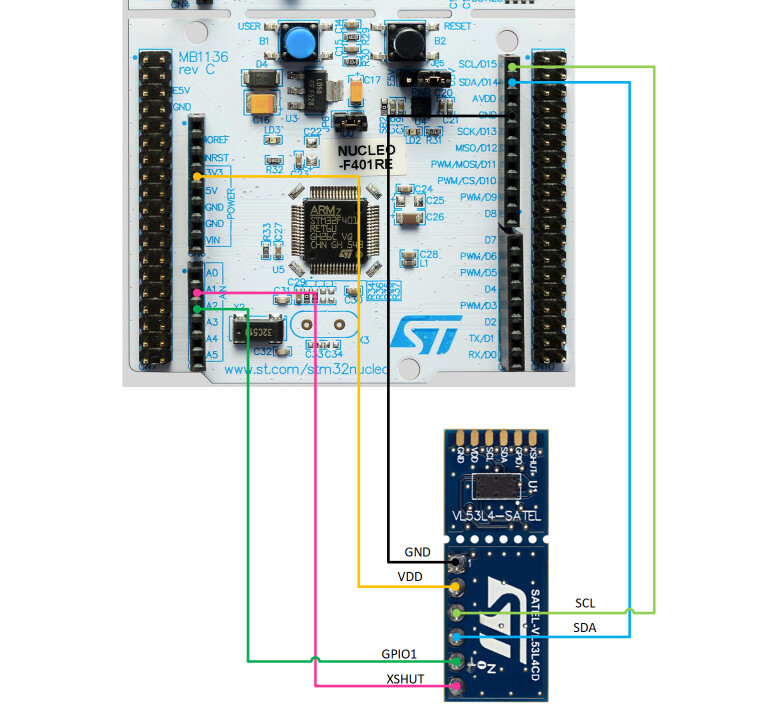
Your hardware connection looks OK, with one possible exception. Looking at your code, it appears you are using polling mode to obtain measurements. In this case, you do not need the connection to GPIO1. In fact, the datasheet recommends not making this connection if it’s not being used.
I see you’ve based your code on the VL53L4CD_ULD driver “CubeIDE_Example”. A few things in your main.c file concern me.
HAL_GPIO_WritePin(GPIOB, TOF_C_XSHUT_Pin, GPIO_PIN_RESET) and HAL_GPIO_WritePin(GPIOB, TOF_C_XSHUT_Pin, GPIO_PIN_SET) (lines 126 and 128) function calls are incorrect as XSHUT is connected to PA1 on your setup.VL53L4CD_CONFIGURATION_LOW_POWER is defined elsewhere in your project? Just making sure status = VL53L4CD_SetRangeTiming(dev, 100, 1000); (line 152) isn’t being ignored…VL53L4CD_ClearInterrupt(dev) (line 165). This operation is required regarless of whether you are using polling mode or the hardware interrupt method. It should not be commented out.printf() statements which are very helpful for debugging. I’d recommend putting them back in.Go ahead and address these issues and re-test your project. If it’s still not working, please provide more information about the failure. What output do you see in the serial console? When you debug the project and single-step through each line of code, where does the unexpected behavior occur?
Fingers crossed!!
Hi @Matt_Mielke thanks for the fast replay,
Here is the updated code
/* USER CODE BEGIN Header */
/**
  ******************************************************************************
  * @file           : main.c
  * @brief          : Main program body
  ******************************************************************************
  * @attention
  *
  * Copyright (c) 2023 STMicroelectronics.
  * All rights reserved.
  *
  * This software is licensed under terms that can be found in the LICENSE file
  * in the root directory of this software component.
  * If no LICENSE file comes with this software, it is provided AS-IS.
  *
  ******************************************************************************
  */
/* USER CODE END Header */
/* Includes ------------------------------------------------------------------*/
#include "main.h"

/* Private includes ----------------------------------------------------------*/
/* USER CODE BEGIN Includes */
#include <stdio.h>
#include "string.h"
#include <math.h>
#include "vl53l4cd_api.h"
#include "vl53l4cd_calibration.h"
/* USER CODE END Includes */

/* Private typedef -----------------------------------------------------------*/
/* USER CODE BEGIN PTD */
#define is_interrupt 1 /*is_interrupt = 1 => get data by interrupt, = 0 => get data by polling */
/* USER CODE END PTD */

/* Private define ------------------------------------------------------------*/
/* USER CODE BEGIN PD */

#define UART_TX_BUFFER_SIZE 32


/* USER CODE END PD */

/* Private macro -------------------------------------------------------------*/
/* USER CODE BEGIN PM */

/* USER CODE END PM */

/* Private variables ---------------------------------------------------------*/
I2C_HandleTypeDef hi2c1;

UART_HandleTypeDef huart2;

/* USER CODE BEGIN PV */
int status;
volatile int IntCount;
uint8_t p_data_ready;
uint16_t dev, sensor_id;
VL53L4CD_ResultsData_t results;		/* Results data from VL53L4CD */
VL53L4CD_Version_t sw_version;	/* Driver version */
/* USER CODE END PV */

/* Private function prototypes -----------------------------------------------*/
void SystemClock_Config(void);
static void MX_GPIO_Init(void);
static void MX_USART2_UART_Init(void);
static void MX_I2C1_Init(void);
/* USER CODE BEGIN PFP */
void get_data_by_polling(uint16_t dev);
void get_data_by_interrupt(uint16_t dev);

/* USER CODE END PFP */

/* Private user code ---------------------------------------------------------*/
/* USER CODE BEGIN 0 */
/* USER CODE END 0 */

/**
  * @brief  The application entry point.
  * @retval int
  */
int main(void)
{
  /* USER CODE BEGIN 1 */
uint16_t buff[50];
uint8_t  loop, isReady;


  /* USER CODE END 1 */

  /* MCU Configuration--------------------------------------------------------*/

  /* Reset of all peripherals, Initializes the Flash interface and the Systick. */
  HAL_Init();

  /* USER CODE BEGIN Init */

  /* USER CODE END Init */

  /* Configure the system clock */
  SystemClock_Config();

  /* USER CODE BEGIN SysInit */

  /* USER CODE END SysInit */

  /* Initialize all configured peripherals */
  MX_GPIO_Init();
  MX_USART2_UART_Init();
  MX_I2C1_Init();
  /* USER CODE BEGIN 2 */

	/* Assign the default address to the sensor */
	dev = 0x52;

	HAL_GPIO_WritePin(GPIOA, XSHUT_Pin, GPIO_PIN_RESET);
	HAL_Delay(5);
	HAL_GPIO_WritePin(GPIOA, XSHUT_Pin, GPIO_PIN_SET);
	HAL_Delay(5);
		status = VL53L4CD_GetSWVersion(&sw_version);
		printf("Starting VL53L4CD driver version %u.%u.%u\n",
					sw_version.major,
					sw_version.minor,
					sw_version.build);
		/* Check if VL53L4CD is connected. 0xebaa is the sensor id. */
		status = VL53L4CD_GetSensorId(dev, &sensor_id);

			if(status || (sensor_id != 0xebaa))
			{
				printf("VL53L4CD not detected\n");
				return status;
			}
		status = VL53L4CD_SensorInit(dev);
		status = VL53L4CD_SetRangeTiming(dev, 100, 1000);
		printf("Ranging starts\n");
		status = VL53L4CD_StartRanging(dev);
  /* USER CODE END 2 */

  /* Infinite loop */
  /* USER CODE BEGIN WHILE */
  while (1)
  {status = VL53L4CD_CheckForDataReady(dev, &p_data_ready);
	if(p_data_ready){

		/* (Mandatory) Clear HW interrupt to restart measurements */
		VL53L4CD_ClearInterrupt(dev);

		/* Read measured distance. RangeStatus = 0 means valid data */
		VL53L4CD_GetResult(dev, &results);
		printf("Status = %3u, Distance = %5u mm, Signal = %6u kcps/spad\n",
				results.range_status,
				results.distance_mm,
				results.signal_per_spad_kcps);
		sprintf((char*)buff,"%.2f\r\n ",results.distance_mm); // @suppress("Float formatting support")
		HAL_UART_Transmit(&huart2,  buff, strlen( (char*)buff ), 0xFFFF );
	}else{
		HAL_Delay(5);
	}
    /* USER CODE END WHILE */

    /* USER CODE BEGIN 3 */
  }
  /* USER CODE END 3 */
}

/**
  * @brief System Clock Configuration
  * @retval None
  */
void SystemClock_Config(void)
{
  RCC_OscInitTypeDef RCC_OscInitStruct = {0};
  RCC_ClkInitTypeDef RCC_ClkInitStruct = {0};

  /** Configure the main internal regulator output voltage
  */
  __HAL_RCC_PWR_CLK_ENABLE();
  __HAL_PWR_VOLTAGESCALING_CONFIG(PWR_REGULATOR_VOLTAGE_SCALE3);

  /** Initializes the RCC Oscillators according to the specified parameters
  * in the RCC_OscInitTypeDef structure.
  */
  RCC_OscInitStruct.OscillatorType = RCC_OSCILLATORTYPE_HSI;
  RCC_OscInitStruct.HSIState = RCC_HSI_ON;
  RCC_OscInitStruct.HSICalibrationValue = RCC_HSICALIBRATION_DEFAULT;
  RCC_OscInitStruct.PLL.PLLState = RCC_PLL_ON;
  RCC_OscInitStruct.PLL.PLLSource = RCC_PLLSOURCE_HSI;
  RCC_OscInitStruct.PLL.PLLM = 16;
  RCC_OscInitStruct.PLL.PLLN = 336;
  RCC_OscInitStruct.PLL.PLLP = RCC_PLLP_DIV4;
  RCC_OscInitStruct.PLL.PLLQ = 2;
  RCC_OscInitStruct.PLL.PLLR = 2;
  if (HAL_RCC_OscConfig(&RCC_OscInitStruct) != HAL_OK)
  {
    Error_Handler();
  }

  /** Initializes the CPU, AHB and APB buses clocks
  */
  RCC_ClkInitStruct.ClockType = RCC_CLOCKTYPE_HCLK|RCC_CLOCKTYPE_SYSCLK
                              |RCC_CLOCKTYPE_PCLK1|RCC_CLOCKTYPE_PCLK2;
  RCC_ClkInitStruct.SYSCLKSource = RCC_SYSCLKSOURCE_PLLCLK;
  RCC_ClkInitStruct.AHBCLKDivider = RCC_SYSCLK_DIV1;
  RCC_ClkInitStruct.APB1CLKDivider = RCC_HCLK_DIV2;
  RCC_ClkInitStruct.APB2CLKDivider = RCC_HCLK_DIV1;

  if (HAL_RCC_ClockConfig(&RCC_ClkInitStruct, FLASH_LATENCY_2) != HAL_OK)
  {
    Error_Handler();
  }
}

/**
  * @brief I2C1 Initialization Function
  * @param None
  * @retval None
  */
static void MX_I2C1_Init(void)
{

  /* USER CODE BEGIN I2C1_Init 0 */

  /* USER CODE END I2C1_Init 0 */

  /* USER CODE BEGIN I2C1_Init 1 */

  /* USER CODE END I2C1_Init 1 */
  hi2c1.Instance = I2C1;
  hi2c1.Init.ClockSpeed = 100000;
  hi2c1.Init.DutyCycle = I2C_DUTYCYCLE_2;
  hi2c1.Init.OwnAddress1 = 0;
  hi2c1.Init.AddressingMode = I2C_ADDRESSINGMODE_7BIT;
  hi2c1.Init.DualAddressMode = I2C_DUALADDRESS_DISABLE;
  hi2c1.Init.OwnAddress2 = 0;
  hi2c1.Init.GeneralCallMode = I2C_GENERALCALL_DISABLE;
  hi2c1.Init.NoStretchMode = I2C_NOSTRETCH_DISABLE;
  if (HAL_I2C_Init(&hi2c1) != HAL_OK)
  {
    Error_Handler();
  }
  /* USER CODE BEGIN I2C1_Init 2 */

  /* USER CODE END I2C1_Init 2 */

}

/**
  * @brief USART2 Initialization Function
  * @param None
  * @retval None
  */
static void MX_USART2_UART_Init(void)
{

  /* USER CODE BEGIN USART2_Init 0 */

  /* USER CODE END USART2_Init 0 */

  /* USER CODE BEGIN USART2_Init 1 */

  /* USER CODE END USART2_Init 1 */
  huart2.Instance = USART2;
  huart2.Init.BaudRate = 115200;
  huart2.Init.WordLength = UART_WORDLENGTH_8B;
  huart2.Init.StopBits = UART_STOPBITS_1;
  huart2.Init.Parity = UART_PARITY_NONE;
  huart2.Init.Mode = UART_MODE_TX_RX;
  huart2.Init.HwFlowCtl = UART_HWCONTROL_NONE;
  huart2.Init.OverSampling = UART_OVERSAMPLING_16;
  if (HAL_UART_Init(&huart2) != HAL_OK)
  {
    Error_Handler();
  }
  /* USER CODE BEGIN USART2_Init 2 */

  /* USER CODE END USART2_Init 2 */

}

/**
  * @brief GPIO Initialization Function
  * @param None
  * @retval None
  */
static void MX_GPIO_Init(void)
{
  GPIO_InitTypeDef GPIO_InitStruct = {0};

  /* GPIO Ports Clock Enable */
  __HAL_RCC_GPIOC_CLK_ENABLE();
  __HAL_RCC_GPIOH_CLK_ENABLE();
  __HAL_RCC_GPIOA_CLK_ENABLE();
  __HAL_RCC_GPIOB_CLK_ENABLE();

  /*Configure GPIO pin Output Level */
  HAL_GPIO_WritePin(GPIOA, XSHUT_Pin|GPIO_PIN_4|LD2_Pin, GPIO_PIN_RESET);

  /*Configure GPIO pin : B1_Pin */
  GPIO_InitStruct.Pin = B1_Pin;
  GPIO_InitStruct.Mode = GPIO_MODE_IT_FALLING;
  GPIO_InitStruct.Pull = GPIO_NOPULL;
  HAL_GPIO_Init(B1_GPIO_Port, &GPIO_InitStruct);

  /*Configure GPIO pins : XSHUT_Pin PA4 LD2_Pin */
  GPIO_InitStruct.Pin = XSHUT_Pin|GPIO_PIN_4|LD2_Pin;
  GPIO_InitStruct.Mode = GPIO_MODE_OUTPUT_PP;
  GPIO_InitStruct.Pull = GPIO_NOPULL;
  GPIO_InitStruct.Speed = GPIO_SPEED_FREQ_LOW;
  HAL_GPIO_Init(GPIOA, &GPIO_InitStruct);

}

/* USER CODE BEGIN 4 */
void get_data_by_interrupt(uint16_t dev){
	do
	{
		__WFI();	// Wait for interrupt
		if(IntCount !=0 ){
			IntCount=0;

			/* (Mandatory) Clear HW interrupt to restart measurements */
			VL53L4CD_ClearInterrupt(dev);

			/* Read measured distance. RangeStatus = 0 means valid data */
			VL53L4CD_GetResult(dev, &results);
			printf("Status = %3u, Distance = %5u mm, Signal = %6u kcps/spad\n",
					results.range_status,
					results.distance_mm,
					results.signal_per_spad_kcps);
		}
	}while(1);
}


void get_data_by_polling(uint16_t dev){
	do
	{
		status = VL53L4CD_CheckForDataReady(dev, &p_data_ready);
		if(p_data_ready){

			/* (Mandatory) Clear HW interrupt to restart measurements */
			VL53L4CD_ClearInterrupt(dev);

			/* Read measured distance. RangeStatus = 0 means valid data */
			VL53L4CD_GetResult(dev, &results);
			printf("Status = %3u, Distance = %5u mm, Signal = %6u kcps/spad\n",
					results.range_status,
					results.distance_mm,
					results.signal_per_spad_kcps);
		}else{
			HAL_Delay(5);
		}
	}
	while(1);
}
/* USER CODE END 4 */

/**
  * @brief  This function is executed in case of error occurrence.
  * @retval None
  */
void Error_Handler(void)
{
  /* USER CODE BEGIN Error_Handler_Debug */
  /* User can add his own implementation to report the HAL error return state */
  __disable_irq();
  while (1)
  {
  }
  /* USER CODE END Error_Handler_Debug */
}

#ifdef  USE_FULL_ASSERT
/**
  * @brief  Reports the name of the source file and the source line number
  *         where the assert_param error has occurred.
  * @param  file: pointer to the source file name
  * @param  line: assert_param error line source number
  * @retval None
  */
void assert_failed(uint8_t *file, uint32_t line)
{
  /* USER CODE BEGIN 6 */
  /* User can add his own implementation to report the file name and line number,
     ex: printf("Wrong parameters value: file %s on line %d\r\n", file, line) */
  /* USER CODE END 6 */
}
#endif /* USE_FULL_ASSERT */
i have updated the set up
but i cannot see where the printf statement pops up i am using PuTTy for the communication
Through the debugging process i see that the it doesn’t even get to the while (1) loop.
it goes through the status = VL53L4CD_GetSWVersion(&sw_version); func
but then it goes and eventually fails at VL53L4CD_GetSensorId(dev, &sensor_id);
func

Hello after careful observation I concluded that platform.c file was different in my code and in the example code so i replaced the code from the example and everything turned out great. But here is still the question how to use printf statements and get them on the serial com
That’s good to hear! For using printf(), I would start with the following guide:
If you’re still having trouble receiving output with PuTTY, please attach a screenshot of your session configuration. I would also suggest trying another serial monitor application and see if you get the same results. TeraTerm is very popular and simpler to use than PuTTY.
Hello! I am currently using the STM32F103C8T6 development board to read data from an optical flow module. While trying to debug the VL53L1X module, I came across your post and attempted to follow the methods you described. However, unfortunately, the module failed to initialize successfully. I suspect that there might be an error in my operating procedure or a problem with the hardware connections. Since I am unable to resolve this issue on my own, I am seeking your help. If it is convenient for you, could you please help me identify where the problem might be? Thank you very much for your assistance!
vl53l1x1_yingjian2.zip (14.8 MB)
ATK-PMW3901光流模块用户手册(兼容2m和4m激光传感器)_V1.1.pdf (1.2 MB)
Hello @690969913,
Sure, I’d be happy to help. Thank you for attaching the project. I’ve got it open and am looking it over. When you debug and single-step through the initialization, where exactly does the failure occur?
Also, would you be able to provide a wiring diagram of your connections between the dev boards? A photo of your setup would be very helpful as well.
Thanks,
Matt
Hi Matt,
Thank you for your prompt response and assistance.
The issue I’m encountering now seems to be that the chip is not initializing properly; the chip ID and distance readings are always garbled.
Best regards
Hi Matt,
Thank you for your prompt response and assistance.
The issue I’m encountering now seems to be that the chip is not initializing properly; the chip ID and distance readings are always garbled.
Thank you again for your support.
Best regards
ATK-PMW3901光流模块用户手册(兼容2m和4m激光传感器)_V1.1.pdf (1.2 MB)
Hi @690969913,
Thanks for the update. I just want to verify… your PMW3901 module is the 4m version, correct? The photo you included is showing the 2m version, which utilizes the VL53L0X sensor.
Thank you for your reply. The board I purchased is the 4m version, and it uses the VL53L1X sensor. Their internal circuit diagrams are the same.