The VL53L5CX is a multizone ranging Time-of-Flight (ToF) sensor capable of producing ranging data in either 4 x 4 or 8 x 8 separate zones. Each zone can detect up to four targets and provide distance measurements up to four meters. The maximum ranging frequency is 60 Hz when configured with 4 x 4 resolution and 15 Hz when configured with 8 x 8 resolution. The driver supports many additional features such as crosstalk calibration when coverglass is used, object threshold detection for low-power operation, and motion detection.

The driver for the VL53L5CX comes in two flavors. The ULD API is a bare-bones, optimized collection of C functions with only three files required for basic functionality. On the other hand, the X-CUBE-TOF1 expansion software package includes several additional layers of abstraction and example applications, making it ideal for prototyping with the X-NUCLEO-53L5A1 expansion board and/or the VL53L5CS-SATEL satellite board(s). The X-CUBE-TOF1 package is well-integrated into the STM32CubeMX code configurator software and thorough getting started instructions are included in UM2853. Therefore, this article will focus on the ULD API as it requires a bit more manual work to add the driver to the project. The last section also provides resources to recreate the example project shown in the animation above.
Requirements
Before getting started, the following firmware, software, and hardware items should be acquired.
- STSW-IMG023 (Version 1.3.6 used in this tutorial)
- This package contains the platform independent VL53L5CX ULD driver files (written in C). It can be found here .
- A Nucleo board
- Though the NUCLEO-F401RE board was used in this tutorial, any Nucleo board will work (though the instructions may have to be altered slightly). Note that a USB cable is not included.
- X-NUCLEO-53L1A1
- An expansion board for evaluating the VL53L5CX module. It can be purchased here .
- STM32CubeIDE (Version 1.11.2 used in this tutorial)
- Feel free to use another IDE if you prefer, e.g. Keil, IAR, etc. I wholeheartedly recommend using STM32CubeIDE, though. Especially if you are new to STM32 development. It may be downloaded from here
Configure the STM32 Device
-
If not done already, create a new STM32CubeIDE project (File > New > STM32 Project). Select your target device using either the MCU/MPU Selector or Board Selector tabs. For this tutorial, I chose the NUCLEO-F401RE development board because it’s what’s included with the P-NUCLEO-53L5A1 evaluation kit . Give your project a name and click Finish.
-
Using the Device Configurator Tool (double click the
.iocfile in the Project Explorer to launch it if it didn’t open automatically), configure the device to interface with the VL53L5CX sensor. Start by configuring the device’s GPIO pins for the I2C instance, external interrupt signal, and enable/reset lines in the Pinout view. For this example, I used the center module on the X-NUCLEO-53L5A1 expansion board, and therefore configured my device based on the schematic diagram provided in Figure 2 of UM2889 (see Table 1 below). My final pinout configuration is shown in Figure 1.
Table 1: GPIO configuration for the center module of the X-NUCLEO-53L5A1 expansion board
| X-NUCLEO-53L5CX Signal Name | Arduino Pin | NUCLEO-F401RE Pin | Pin Configuration |
|---|---|---|---|
| I2C_RST_C | D3 | PB3 | GPIO_Output |
| LPn_C | D5 | PB4 | GPIO_Output |
| PWR_EN_C | A3 | PB0 | GPIO_Output |
| INT_C | A2 | PA4 | GPIO_EXTIx |
| SCL | D15 | PB8 | I2Cx_SCL |
| SDA | D14 | PB9 | I2Cx_SDA |

- From the Components List on the left, choose the I2C peripheral corresponding to the SDA and SCL pins configured in the previous step. For my device, I chose I2C1. In the Mode panel, select “I2C” from the drop-down list for the I2C setting. Note that after doing this, the SDA and SCL pins in the Pinout View should change from yellow to green. In the Configuration panel, select “Fast Mode” from the drop-down list for the I2C Speed Mode setting. The final I2C configuration should resemble that shown in Figure 2.

- Select the GPIO peripheral from the Components List and change the GPIO Output Level to “High” for the PWR_EN_C and LPn_C pins. For the INT_C pin, change the GPIO mode to “External Interrupt Mode with Falling edge trigger detection”. Note that the default “No pull-up and no pull-down” setting for the INT_C pin is left unchanged because there is a 47 kΩ pull-up resistor mounted on the X-NUCLEO-53L5A1 board (R5). Optionally, add the corresponding User Labels to the VL53L5CX interface pins for clarity. Each of these changes to the GPIO settings is highlighted in Figure 3 below.

- Under the NVIC tab, check the box next to the EXTI Line corresponding to the INT_C pin as shown in Figure 4.

- Save the
.iocfile to generate code for the project.
Add the Driver
Again, this tutorial explains how to add and utilize the VL53L5CX ULD API. If you would rather use the X-CUBE-TOF1 package, please follow the instructions provided in UM2853.
-
Download the ULD API and extract the file to your desired location. At the time of writing, version 1.3.6 is the most recent release.
-
In STM32CubeIDE, right-click on the Drivers folder in the Project Explorer and select Import. Using the Import Wizard, choose File System from the General category. Click Next.
-
Populate the “From Directory:” field with the path to the ULD driver:
<extraction_location>/VL53L5CX_ULD_driver_1.3.0. As shown in Figure 5, select all resources in the VL53L5CX_ULD_API directory. Click Finish.

-
Right-click on
Drivers/VL53L5CX_ULD_API/incdirectory in the Project Explorer. Select Add/remove include path… and click OK. -
Copy and paste the example platform files into the project.
-
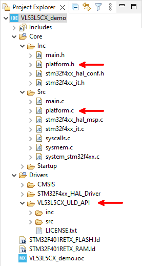
Copy
<extraction_location>/VL53L5CX_ULD_driver_1.3.6/CubeIDE_F401RE_Example/Core/Inc/platform.hand paste it intoCore/Inc. -
Copy
<extraction_location>/VL53L5CX_ULD_driver_1.3.6/CubeIDE_F401RE_Example/Core/Src/platform.cand paste it intoCore/Src.
The changes made to the directory structure are shown below in Figure 6. To begin using the driver, add the line #include "vl53l5cx_api.h" to the Private includes section of the main.c file. The project should build successfully.
Example Application
The animation shown at the top of this article shows a simple example application using an 8 x 8 NeoPixel matrix. A still image of the hardware setup is shown below in Figure 7. An external 5V (2A) power supply is connected to E5V on the Nucleo Board and the +5V pin supplies power to the NeoPixel matrix. Pin PB10 (D6 on the Arduino headers) provides the NeoPixel control signal and, thus, is connected to DIN on the matrix. For detailed information on generating the NeoPixel control signal, see Controlling NeoPixels with STM32.

To power up the Nucleo board, the proper startup sequence must be followed!
-
Ensure JP5 is in the E5V position (between pins 2 and 3)
-
Ensure JP1 is removed
-
Connect and power on the external 5V power source
-
Check that LD3 is on
-
Connect the PC to the ST-LINK USB connector (CN1)
I highly recommend reading section 6.3 of UM1724 before using an external power source to avoid damaging your board!
The main.c file for this application is available on the project’s GitHub Repository. Note that the printf statements are enabled using the method described in Easily Use printf on STM32.


