High-level development platforms, such as Arduino and Feather boards, already provide outstanding support for interfacing with NeoPixel LEDs, strips, matrices, etc. via easy to use libraries and prevalent example code. Unfortunately, the same level of assistance is generally not available for more advanced platforms, such as STM32 development boards. As such, developers wishing to incorporate NeoPixels into their project are required to fully understand the NeoPixel communication protocol and how to overcome the challenges it presents.

NeoPixels
The extremely popular line of addressable full-color LEDs branded by Adafruit as “NeoPixels” are available in either RGB or RGBW varieties. While both options integrate red, green, and blue LEDs with a driver chip; the RGBW components also integrate a fourth LED which is pure white. A similar single-wire serial interface is used to control both NeoPixel types with only minor differences in the timing values and data structures of the protocols.
WS2812
The RGB NeoPixels are actually WS2812 intelligent control LEDs, which include a data signal input pin (DIN) and a data signal output pin (DOUT). This allows multiple LEDs to be cascaded and controlled with only a single data line. The first LED in the chain processes the first three bytes of data it receives from the MCU and simply forwards any subsequent data to the DOUT pin, which may be connected to the DIN pin of another LED. The LEDs will continue passing data down the line in this manner until they receive the reset signal (i.e., the DIN line is held low for a certain length of time). The transmitted bytes are organized according the the protocol shown in Figure 1. The first byte (G7-G0) represents the 8-bit PWM intensity of the green LED, where 0x00 is fully off and 0xFF is fully on. Similarly, the second byte (R7-R0) controls the intensity of the red LED and the third (B7-B0) does the same for the blue LED.
![]()
Figure 1: Structure of the 3-byte data protocol for the WS2812 LEDs.
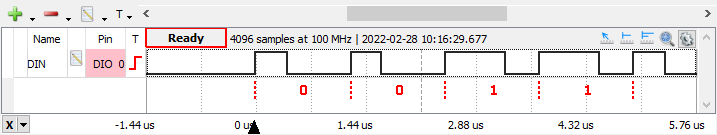
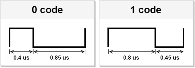
Each of these 24 bits are encoded by varying the pulse widths of a square wave as illustrated in Figure 2. Notice that whether a 0 code is sent or a 1 code is sent, the period of the square wave remains fixed at 1.25 μs. For the WS2812, the reset signal is generated by holding the data line low for at least 50 μs. Note also that the timing values indicated in Figure 2 have a tolerance of ±0.15 μs.
SK6812
A different component entirely, the RGBW variety of NeoPixels are really SK6812 intelligent control LEDs, which operate on the same principal as the WS2812 LEDs. However, because they include a fourth LED, they implement the 4-byte data protocol shown in Figure 3. Compared to Figure 1, the only difference is the concatenated byte of data (W7-W0) specifying the 8-bit PWM intensity of the white LED.
![]()
Figure 3: Structure of the 4-byte data protocol for the SK6812 LEDs.
Figure 4 shows that the timing values of the SK6812 control signal also vary slightly from those of the WS2812 (though the ±0.15 μs tolerance still applies). This time, notice that for both codes, the period of the square wave remains fixed at 1.2 μs. Furthermore, the length of the SK6812’s reset signal is 80 μs rather than 50 μs.

Procedure
Due to the tight timing requirements of the NeoPixel’s control signal, it cannot feasibly be produced by a simple bit-banging approach unless assembly language is used. While there are many other strategies for generating said signal utilizing various MCU peripherals, external hardware, or combinations thereof; the most straightforward of these is to configure an MCU timer to generate a PWM output signal. This is because, as pointed out in the previous section, the NeoPixel control signal is simply a fixed-frequency PWM signal with different duty cycles for the 0 and 1 bits. In order to efficiently switch between these two duty cycles at the same rate as the transmission protocol, a DMA stream must also be configured to manage the updates. Though this method is likely the least memory efficient; it is simple to understand, CPU efficient, and easy to implement (thanks to the STM32Cube environment).
The following procedure realizes the above method utilizing STM32CubeIDE (version 1.8.0), an NUCLEO-F401RE development board, and an RGBW 5x8 NeoPixel Shield. However, the steps can easily be generalized to any STM32 MCU/board and NeoPixel product. It is assumed that an STM32CubeIDE project has already been created. If another IDE is preferred, the standalone STM32CubeMX code configurator tool can be used instead of STM32CubeIDE to export the project to the desired development platform.
1. Configure PWM
a. If not already done, start by opening the STM32CubeMX configuration .ioc file. This will cause STM32CubeIDE to switch to the Device Configuration Tool perspective where the MCU can be configured.
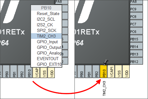
b. Assign a timer channel alternate function to the GPIO pin chosen to interface with the NeoPixel(s). The timer channel selected should be capable of PWM output generation. Figure 5 shows that for my project, I’m selecting pin PB10 and assigning to it the Timer 2, Channel 3 (TIM2_CH3) function.
c. Select the timer peripheral identified in the previous step from the component list on the left to open the Mode and Configuration panels. In the Mode panel, choose “Internal Clock” as the Clock Source and choose “PWM Generation CHx” from the drop-down list for the appropriate timer channel. In Figure 6, Timer 2, Channel 3 is set to “PWM Generation CH3” mode because I chose the TIM2_CH3 alternate function in the previous step. Note that after completing this step, the associated GPIO pin should change from yellow to green in the Pinout view.
d. In the timer’s Configuration panel, verify that the “Prescaler” and “Pulse” values are both set to 0. The Counter Period, a.k.a. AutoReload Register (ARR), needs to be set to achieve the required PWM period (1.25 μs if using the RGB WS2812 LEDs or 1.2 μs if using the RGBW SK6812 LEDs). This will depend on the rate at which the timer peripheral is being clocked. Simply divide the desired PWM period by the clock period and subtract 1 to get this value (we subtract by 1 because the counter starts at 0). For my device, this calculation yields an ARR value of 99.8, which I rounded up to 100 (Figure 6). See below for a detailed explanation of calculating the ideal ARR value.

Calculating the ARR Value
Assuming that the timer “Prescaler” value is set to 0, the ARR value can simply be calculated as
That is, the ARR value is the period of the PWM signal divided by the period of the timer peripheral’s clock signal. We know that T_{PWM} is either 1.25 μs or 1.2 μs depending on which NeoPixel variety is being utilized (for this example, T_{PWM} = 1.2 \mu{}s). To determine T_{timer}, you may have to consult your devices datasheet to determine which bus your timer peripheral is connected to. The datasheet can either be found on ST’s website or with STM32CubeIDE by choosing Help > Target Device Docs and Resources. Then, select the datasheet under the MCU tab, as demonstrated in Figure 7.

In the datasheet for my MCU (the STM32F401RE), the device block diagram shows that my timer (TIM2) is connected to APB1 (see Figure 8).

Figure 9 explains that by switching to the Clock Configuration tab in STM32CubeIDE, we discover that TIM2 is clocked at 84 MHz (T_{timer} = \frac{1}{f_{timer}} = \frac{1}{84\text{ MHz}})

Thus,
To get the PWM period as close to the period of the NeoPixel control signal as possbile, we round to the nearest whole number and get ARR = 100.
2. Configure DMA
a. From the component list, select the DMA peripheral.
b. Under the DMA1 tab in the Configuration panel, click the Add button. In the dropdown menu, choose your timer/channel combination. For my project, I chose “TIM2_CH3/UP”.
c. For this new DMA request, change the direction to “Memory To Peripheral”.
d. Also, change the priority to “Very High”.
e. Verify that the default DMA request settings match those shown in Figure 10.
f. Save the .ioc file to generate code for the project.

3. Write the Code
Working from the top-down in the main.c file, this section presents a simple example application to test the full-color capabilities of the NeoPixel LEDs. Two versions of the main() function are provided; one for the RGB WS2818 LEDs and one for the RGBW SK6812 LEDs.
a. In the Private typedef section of the main.c file, it is helpful to create a new datatype to facilitate easy access to the individual LED color values as well as the entire NeoPixel data structure (shown in Figures 1 and 3). Listing 1 provides typedefs for both the RGB and RGBW NeoPixel components. This code should by pasted between the /* USER CODE BEGIN PTD */ and /* USER CODE END PTD */ comments.
Listing 1: Custom data types for both the RGB WS2812 and RGBW SK6812 LEDs
typedef union
{
  struct
  {
    uint8_t b;
    uint8_t r;
    uint8_t g;
  } color;
  uint32_t data;
} PixelRGB_t;

typedef union
{
  struct
  {
    uint8_t w;
    uint8_t b;
    uint8_t r;
    uint8_t g;
  } color;
  uint32_t data;
} PixelRGBW_t;
b. Changing the value of the “Pulse” register (a.k.a., CCRx) is what changes the duty cycle of the PWM waveform. Therefore, we must calculate the appropriate CCRx values to achieve the 0 code and 1 code square waves required by the utilized NeoPixels (either those shown in Figure 2 or Figure 4). For the RGB WS2812 LEDs, these values are calculated as follows:
For the RGBW SK6812 LEDs, the calculations are slightly different.
Of course, these calculated values should be rounded to the nearest whole number. In the Private defines section of the main.c file, create a #define directive for each value (see the example below in Figure 11).
c. In addition to the CCRx values, the number of NeoPixel LEDs being controlled and the DMA buffer size should be defined in the Private defines section as well. As shown in Figure 11, simply multiply the number of LEDs by the number of bits in the corresponding NeoPixel data structure (recall Figures 1 and 3). An extra buffer element must be allotted as well because the last CCRx value should be zero (the reset signal).

d. Add the DMA Finished Callback function provided in Listing 2 to the Private user code section between /* USER CODE BEGIN 0 */ and /* USER CODE END 0*/. Be sure to change TIM_CHANNEL_x to the channel configured in Step 1c.
Listing 2: Implementation of the HAL_TIM_PWM_PulseFinishedCallback() function
void HAL_TIM_PWM_PulseFinishedCallback(TIM_HandleTypeDef *htim)
{
  HAL_TIM_PWM_Stop_DMA(htim, TIM_CHANNEL_x);
}
e. Finally, the application code must be added to the main() function. Listing 3 provides one example main() function utilizing WS2812 LEDs and Listing 4 provides a similar example main() function utilizing SK6812 LEDs. Note that the TIM_CHANNEL_x argument to the HAL_TIM_PWM_Start_DMA() function must again be modified to match the channel configured in Step 1c.
Listing 3: Example main() function for RGB WS2812 LEDs
int main(void)
{
  /* USER CODE BEGIN 1 */

  PixelRGB_t pixel[NUM_PIXELS] = {0};
  uint32_t dmaBuffer[DMA_BUFF_SIZE] = {0};
  uint32_t *pBuff;
  int i, j, k;
  uint16_t stepSize;

  /* USER CODE END 1 */

  /* MCU Configuration--------------------------------------------------------*/

  /* Reset of all peripherals, Initializes the Flash interface and the Systick. */
  HAL_Init();

  /* USER CODE BEGIN Init */

  /* USER CODE END Init */

  /* Configure the system clock */
  SystemClock_Config();

  /* USER CODE BEGIN SysInit */

  /* USER CODE END SysInit */

  /* Initialize all configured peripherals */
  MX_GPIO_Init();
  MX_USART2_UART_Init();
  MX_DMA_Init();
  MX_TIM2_Init();
  /* USER CODE BEGIN 2 */

  /* USER CODE END 2 */

  /* Infinite loop */
  /* USER CODE BEGIN WHILE */
  k = 0;
  stepSize = 4;
  while (1)
  {
    /* USER CODE END WHILE */

    /* USER CODE BEGIN 3 */

    for (i = (NUM_PIXELS - 1); i > 0; i--)
    {
      pixel[i].data = pixel[i-1].data;
    }

    if (k < 255)
    {
      pixel[0].color.g = 254 - k; //[254, 0]
      pixel[0].color.r =  k + 1;  //[1, 255]
      pixel[0].color.b = 0;
    }
    else if (k < 510)
    {
      pixel[0].color.g = 0;
      pixel[0].color.r = 509 - k; //[254, 0]
      pixel[0].color.b = k - 254; //[1, 255]
      j++;
    }
    else if (k < 765)
    {
      pixel[0].color.g = k - 509; //[1, 255];
      pixel[0].color.r = 0;
      pixel[0].color.b = 764 - k; //[254, 0]
    }
    k = (k + stepSize) % 765;

    // not so bright
    pixel[0].color.g >>= 2;
    pixel[0].color.r >>= 2;
    pixel[0].color.b >>= 2;

    pBuff = dmaBuffer;
    for (i = 0; i < NUM_PIXELS; i++)
    {
       for (j = 23; j >= 0; j--)
       {
         if ((pixel[i].data >> j) & 0x01)
         {
           *pBuff = NEOPIXEL_ONE;
         }
         else
         {
           *pBuff = NEOPIXEL_ZERO;
         }
         pBuff++;
     }
    }
    dmaBuffer[DMA_BUFF_SIZE - 1] = 0; // last element must be 0!

    HAL_TIM_PWM_Start_DMA(&htim2, TIM_CHANNEL_x, dmaBuffer, DMA_BUFF_SIZE);

    HAL_Delay(10);
  }
  /* USER CODE END 3 */
}
Listing 4: Example main() function for RGBW SK6812 LEDs
int main(void)
{
  /* USER CODE BEGIN 1 */

  PixelRGBW_t pixel[NUM_PIXELS] = {0};
  uint32_t dmaBuffer[DMA_BUFF_SIZE] = {0};
  uint32_t *pBuff;
  int i, j, k;
  uint16_t stepSize;

  /* USER CODE END 1 */

  /* MCU Configuration--------------------------------------------------------*/

  /* Reset of all peripherals, Initializes the Flash interface and the Systick. */
  HAL_Init();

  /* USER CODE BEGIN Init */

  /* USER CODE END Init */

  /* Configure the system clock */
  SystemClock_Config();

  /* USER CODE BEGIN SysInit */

  /* USER CODE END SysInit */

  /* Initialize all configured peripherals */
  MX_GPIO_Init();
  MX_USART2_UART_Init();
  MX_DMA_Init();
  MX_TIM2_Init();
  /* USER CODE BEGIN 2 */

  /* USER CODE END 2 */

  /* Infinite loop */
  /* USER CODE BEGIN WHILE */
  k = 0;
  stepSize = 4;
  while (1)
  {
    /* USER CODE END WHILE */

    /* USER CODE BEGIN 3 */

    for (i = (NUM_PIXELS - 1); i > 0; i--)
    {
      pixel[i].data = pixel[i-1].data;
    }

    if (k < 255)
    {
      pixel[0].color.g = 254 - k; //[254, 0]
      pixel[0].color.r =  k + 1;  //[1, 255]
      pixel[0].color.b = 0;
      pixel[0].color.w = 0;
    }
    else if (k < 510)
    {
      pixel[0].color.g = 0;
      pixel[0].color.r = 509 - k; //[254, 0]
      pixel[0].color.b = k - 254; //[1, 255]
      pixel[0].color.w = 0;
      j++;
    }
    else if (k < 765)
    {
      pixel[0].color.g = 0;
      pixel[0].color.r = 0;
      pixel[0].color.b = 764 - k; //[254, 0]
      pixel[0].color.w = k - 509; //[1, 255]
    }
    else if (k < 1020)
    {
      pixel[0].color.g = k - 764; //[1, 255]
      pixel[0].color.r = 0;
      pixel[0].color.b = 0;
      pixel[0].color.w = 1019 - k; //[254, 0]
    }
    k = (k + stepSize) % 1020;

    // 50% brightness
    pixel[0].color.g >>= 2;
    pixel[0].color.r >>= 2;
    pixel[0].color.b >>= 2;
    pixel[0].color.w >>= 2;

    pBuff = dmaBuffer;
    for (i = 0; i < NUM_PIXELS; i++)
    {
       for (j = 31; j >= 0; j--)
       {
         if ((pixel[i].data >> j) & 0x01)
         {
           *pBuff = NEOPIXEL_ONE;
         }
         else
         {
           *pBuff = NEOPIXEL_ZERO;
         }
         pBuff++;
     }
    }
    dmaBuffer[DMA_BUFF_SIZE - 1] = 0; // last element must be 0!

    HAL_TIM_PWM_Start_DMA(&htim2, TIM_CHANNEL_x, dmaBuffer, DMA_BUFF_SIZE);

    HAL_Delay(10);
  }
  /* USER CODE END 3 */
}
The project should now build successfully, allowing you to run the code on your device.
Results
Using a logic analyzer, the control signals generated by both the RGB and RGBW configurations provided above were captured. Both are shown below in Figures 12 and 13, respectively. Notice that they match the expected outputs specified in Figures 2 and 4.