Overview
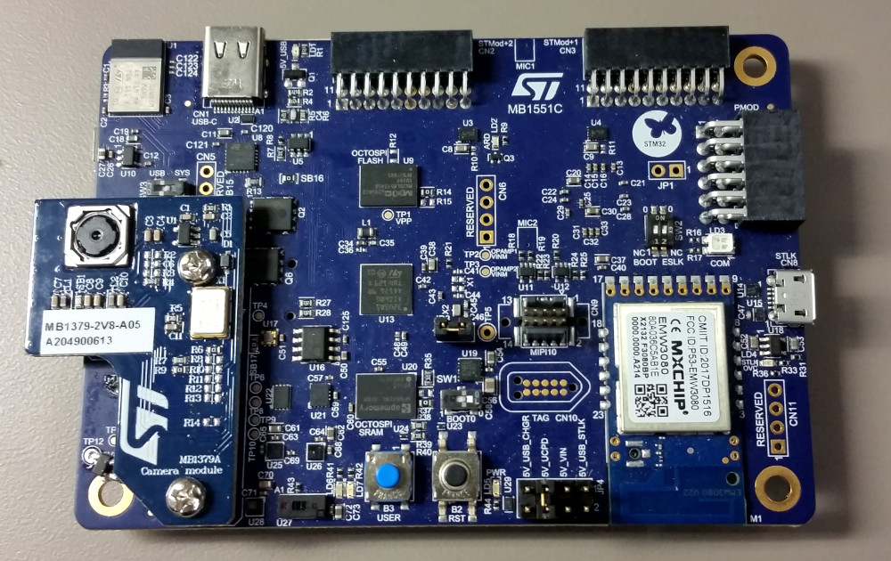
Figure 1: The B-U585I-IOT02A Discovery board with
the UM1379 camera module plugged into the camera
daughterboard connector.
The B-U585I-IOT02A Discovery board from STMicroelectronics is loaded with a variety of sensors, connectivity options, and other features selected to highlight the enhanced capabilities embedded in the focus STM32U5 MCU. Aside from the standard LEDs and push-buttons, these include the following:
- External Memories
- 512-Mbit Quad-SPI Flash
- 64-Mbit Octo-SPI PSRAM
- 256-Kbit I2C EEPROM
- MEMS sensors
- Two digital microphones
- Relative humidity and temperature sensor
- 3-axis magnetometer
- 3D accelerometer and 3D gyroscope
- Pressure sensor
- Time-of-flight and gesture-detection sensor
- Ambient light sensor
- RF modules
- 802.11 b/g/n compliant Wi-Fi® module from MXCHIP
- Bluetooth® Low Energy from STMicroelectronics
- Board connectors
- USB Type-C®
- ARDUINO® Uno V3 expansion connectors
- Camera module expansion connector
- Two STMod+ expansion connectors
- Pmod™ expansion connector
- STSAFE-A110 security and authentication solution
- On-board STLINK-V3E debugger/programmer with USB re-enumeration capability: mass storage, Virtual COM port, and debug port
Several of these features; namely the camera module connector, ToF sensor, and USB Type-C connector; were utilized to create a demo application which utilizes the B-U585I-IOT02A as a rudimentary RGBD (RGB + Depth) imaging device. To achieve this, the B-U585I-IOT02A was paired with the MB1379 camera module (bundled with the B-CAMS-OMV kit) as shown above in Figure 1. In an example of impressive performance achievable by an ultra-low-power device, the STM32U5 MCU collects and transmits RGB images from this module along with the ToF ranging data of the same scene in real-time to a connected PC. It does so by hosting an embedded web server accessible via the USB Type-C port, which is configured as a virtual network adapter. Not only does this provide a universal framework for supplying and formatting the imaging data, it supports the easy creation of a user interface such as the one shown below in Figure 2.

Figure 2: The user interface created for the B-U585I-IOT02A demo application using HTML, CSS, and JavaScript .
Key Components
This demo application is fairly complicated and employs several pieces of external hardware, advanced MCU peripherals, and embedded software components to produce the above result. This section provides a brief description of the most noteworthy of these elements for those who may be interested in implementing something similar. If there is any topic you feel should be discussed in more detail, please create a reply to this post and let us know!
Azure RTOS ThreadX
As of 2021, Microsoft® Azure® RTOS embedded software components are being directly integrated into the STM32Cube MCU packages for all new STM32 series (e.g., the STM32U5 series). That is, Azure RTOS ThreadX is now the RTOS of choice for STM32 applications, taking the place of FreeRTOS. The other Azure RTOS components, including NetX Duo, USBX, FileX, and LevelX, are also taking a prominent position in the ST middleware solution, replacing the LwIP, mbedTLS, ST USB, and FatFS software stacks. This demo application takes full advantage of these components and their tight integration into the STM32Cube ecosystem, including their high level of configurability with STM32CubeMX.
Embedded Web Server
At the heart of this application is the embedded web server created using the Web HTTP addon for the Azure RTOS NetX Duo network stack. With it, two server instances are created. One instance (on port 81) is dedicated to continuously sending JPEG images from the camera module to the client. In doing so, an MJPEG video stream is created. The second server instance (on the default port 80) handles all other client requests such as providing the most recent ranging data from the ToF sensor, enabling/disabling the video stream, and toggling the state of the red LED on the Discovery board. These two server instances are necessary for all operations to run concurrently. The corresponding code can be found in the app_netxduo.c file.
The web server files are stored in an embedded file system located on the internal flash memory of the MCU. This file system was established using Azure RTOS FileX. Note that in a typical scenario where a file system is created in Flash memory, a wear leveling scheme would be implemented because of the limited number of erase operations available for NAND/NOR memories. Azure RTOS does offer the LevelX component for just this purpose. However, wear leveling is not necessary in this application because the web files are only read from file system, not written or modifed. Therefore, Azure RTOS LevelX is not used.
Network Connectivity
To establish a network connection with the discovery board, the USB Type-C port was configured as a virtual network adapter using the USB Communications Device Class (CDC). More specifically, the Ethernet Control Model subclass (ECM) was used to facilitate Ethernet packet transfers over USB. The CDC-ECM device class is supported by the Azure RTOS USBX protocol stack, which in turn works with the Azure RTOS NetX and NetX Duo network stacks to provide access to the embedded web server. The STM32CubeMX code configurator makes it very easy to add the USBX component to the project and select the CDC-ECM device class for the USB device framework. To see for yourself, open the STM32CubeMX configuration file (b-u585i-iot02a_camera_demo.ioc) located in the project’s GitHub repository.
Note that both Linux and MacOS provide native support for the USB CDC-ECM class. However, if you wish to make a network connection to this Discovery board with a Windows PC, a third party CDC-ECM driver is required.
Camera Video Stream
Similar to the usage demonstrated in Using a Camera Module with the B-U585I-IOT02A Discovery Board, the DCMI peripheral on the STM32U5 is used to interface with the camera module and capture the images it provides. For this demo application, however, the image sensor (the OV5640 on the MB1379 camera module) is configured to supply images in JPEG format. These images are much smaller in size compared to those in RGB565 format, which means 1) a double buffering scheme can be used without exceeding the internal SRAM boundaries and 2) the images can be sent to the web client in a timely fashion. The double buffering strategy allows the DMA peripheral to store new images in memory while the previous image is being sent by the web server in parallel.
VL53L5CX Depth Map Data Stream
Using the procedure outlined in Getting Started with the VL53L5CX ToF Sensor, the driver for the VL53L5CX multizone ranging Time-of-Flight (ToF) sensor was added to the project. The API was then used to configure the sensor to continuously capture ranging data with an 8 x 8 resolution and read this data every time a request is made by the web client.
The stream of ranging data is created using a periodically executed JavaScript function which requests the latest data values and uses them to update the color-coded depth map shown in Figures 2 and 8. This depth map is rendered using an HTML canvas element and two text box inputs are used to set some visualization parameters. The “Frequency” parameter allows the user to set the frame rate of the depth map images and the “Max Distance” parameter allows the user to set the maximum distance that can be represented by the color scale. The JavaScript code that produces these results can be found in the index.html file in the project’s GitHub repository.
Run It Yourself
Once you have acquired the hardware and installed the development tools, you can run this demo application yourself and begin building upon it. The requirements are as follows.
- The B-U585I-IOT02A Discovery board
- The B-CAMS-OMV bundle
- Includes the MB1379 camera module and an adapter board
- STM32CubeIDE (version 1.11.2 used below)
- STM32CubeProgrammer (version 2.10.0 used below)
Procedure
-
Download the source code from the project’s GitHub repository.
-
Double-click on the
.projectfile in the project directory (see Figure 3). STM32CubeIDE should start up and request that you select a directory as a workspace. Select your desired directory and click Launch. The project should successfully be imported into the workspace.

- Select the project in the Project Explorer and choose Project > Build Project. The project should successfully build without errors, as shown in Figure 4.

-
Connect the MB1379 camera module to the B-U585I-IOT02A Discovery board as shown in Figure 1. Connect the the Discovery board to the PC using the STLK Micro-B USB connector (CN8). Note that the JP4 jumper should be in the default “5V_USB_STLK” position.
-
In STM32CubeIDE, choose Run > Run. Because this is the first time running the application, the Edit Configuration window should appear. Click OK, leaving the settings unchanged. Wait for the download to complete.
-
Launch the STM32CubeProgrammer application. With the Discovery board still connected to the PC, click the Connect button to connect to the board.
-
Click the + tab and choose Open File. Navigate to the project directory and choose the
web content/web_server.binfile. -
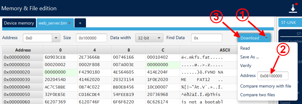
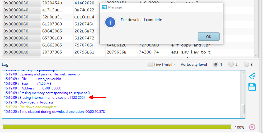
As Figure 5 demonstrates, click on the drop-down arrow next to the Download button. Change the Address value to
0x08100000. Once the address is changed, click on the Download button. You should see that only the internal memory sectors [128 255] have been erased, as pointed out in Figure 6.
-
Once the file download is complete, disconnect the board by clicking the Disconnect button.
-
Open a terminal application (such as Tera Term) and open the STLink Virtual Com Port. Change the baud rate to 115200 and change the new-line behavior to produce the expected result (in Tera Term for instance, choose Setup > Terminal… and change the Receive option to “AUTO”).
-
Press the black reset button on the board and connect it to a PC running Linux or MacOS using the USB Type-C connector (CN1). If you would like to use a PC running Windows, you will either have to install third party CDC-ECM drivers or use a virtual machine. You should see a terminal output similar to that in Figure 7. Note the IP Address for the next step.

- Finally, open a web browser on the PC connected to CN1. In the address bar, enter
<ip_address>/index.html, using the IP address provided in the terminal output. For instance, I use the address10.42.0.86/index.html. The demo user interface should be presented, as shown in Figure 8 Press the Start Stream button to begin streaming video.
