Introduction
The STM32L053 Discovery board from STMicroelectronics features an STM32L053C8 MCU, taken from their STM32L0 ultra-low-power series of microcontrollers. Among other features, this board includes a current measurement module that may be read by the MCU, allowing it to monitor its own current consumption. Unfortunately, the lack of documentation on this feature makes it rather difficult to utilize for evaluation purposes. Thanks to ST’s example code, though, a basic procedure for communicating with the module was established and used to develop a more streamlined example application. Combined with the information from the Low-Power Modes on the STM32L0 Series page, this application allows the user to observe how each low-power mode on the STM32L053C8 affects the MCU’s current consumption.
Background
ST offers three types of development boards: the Nucleo boards, Discovery boards, and Evaluation boards. The Nucleo boards are the simplest and cheapest. Besides including a built in ST-LINK/V2 debugger/programmer like the rest of the development boards, they do little more than break out the I/O lines of the featured MCU and provide a few pushbuttons and LEDs. The Evaluation boards, on the other hand, are far more expensive because they come with all the hardware required to evaluate every feature of the MCU the board is based on. The Discovery boards are a compromise. They come with only the necessary components for demonstrating specific device characteristics. Consider the key features of the STM32L053 Discovery board (Figure 1):
- STM32L053C8T6 microcontroller featuring 64 KB of Flash memory, 8 KB RAM in an LQFP48 package.
- On-board ST-LINK/V2-1 with selection mode switch to use the kit as a standalone ST-LINK/V2-2 (with SWD connector for programming and debugging)
- mbedTM-enabled (mbed.org)
- USB ST-LINK with re-enumeration capability and three different interfaces:
- virtual com port
- mass storage
- debug port
- Board power supply: through USB bus or from an external 5 V supply voltage
- External application power supply: 3 V and 5 V
- One linear touch sensor or four touchkeys
- IDD current measurement
- 2.04" E-paper display, 172X72 pixels
- Four LEDs:
- LD1 (red/green) for USB communication
- LD2 (red) for 3.3 V power-on
- Two user LEDs: SD3 (green), LD4 (red)
- Two pushbuttons (user and reset)
- Extension header for LQFP48 I/Os for a quick connection to the prototyping board and easy probing
- Comprehensive free software including a variety of examples, part of STM32CubeL0 package
The main differences between this board and a similar Nucleo board are the linear touch sensor, IDD current measurement, and E-paper display. This makes sense considering that the featured MCU, i.e. the STM32L053C8, is an ultra-low-power microcontroller with touch sensing capabilities. In the following sections, the IDD measurement module is further explored so it may effectively be used to evaluate the low-power features of the STM32L0 series of MCUs.

The following documents are very helpful when developing applications on the STM32L053 Discovery board:
Measuring Current Consumption
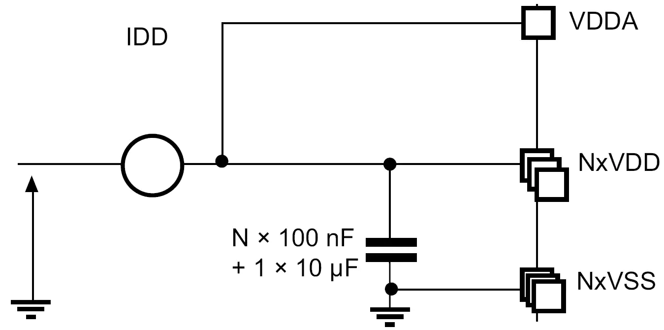
Section 6.1.8 of the STM32L053 datasheet shows that the preferred method of measuring the current consumed by the MCU is a high-side sensing scheme (Figure 2). That is, the current sensing device is placed between the voltage supply and the load (the MCU). The STM32L053 Discovery board uses this approach to implement its current measurement feature. In short, this feature allows the user to measure the current consumed by the STM32L053C8 either by using their own current measurement instrument or by using the onboard current measurement module.
Jumper JP4 on the Discovery board will enable or disable the IDD measurement feature. Figure 3 is a high level representation of how JP4 directs the flow of current. If the jumper is placed over pins 1 and 2 (the OFF position), then VCC is connected directly to the MCU and current cannot be measured. If the jumper is placed over pins 2 and 3 (the ON position), then current will flow from VCC, through the IDD measurement module, and then to the MCU. In this configuration, the MCU can communicate with the module and request the instantaneous current consumption.
In order to measure the current using an external device, like an ammeter, the jumper should be removed entirely. Then, the leads of the instrument should be placed on pins 1 and 2 in order to complete the circuit and still conform to the high-side sensing scheme.

IDD Measurement Module
Once JP4 is in the ON position, the user needs to know how to read the current measurements. The Discovery board’s datasheet provides no information on this topic (other than mentioning that the measurement range is 50 mA to 100 nA). A simple operating procedure was deduced by studying the board’s schematic and demonstration code. The module can plainly be divided into 2 parts: the current sense resistor network and the Multi-Function eXpander (MFX). The resistors create a voltage signal proportional to the rate of current flow, which is amplified before being read by the MFX. Not only does the MFX translate this voltage into a current measurement and report it to the MCU, but it also acts as a controller for the resistor network, configuring the total shunt resistance to the optimal value for the amount of current being consumed by the MCU.
Current Sense Resistors
Figure 4 shows the circuit that measures the current being consumed by the MCU. There are four current sense resistors in this circuit (1Ω, 24Ω, 620Ω, and 10kΩ) that have been highlighted by purple boxes. Three of these resistors are placed in series with MOSFETS whose gates are connected to GPIO pins on the MFX. In this way, the MFX can change the total shunt resistance by turning on various combinations of these MOSFETs. This is necessary to ensure that the amplified voltage across the shunt resistance does not exceed 3.3 V while small changes in current still produce a significant change in voltage. Note that there is a fourth MOSFET connected to the MFX that is used for calibration purposes.
There are four op-amps shown in Figure 4 that are used to amplify the voltage drop across the shunt resistance. The two labeled U7B and U7D are simply used as voltage followers in order to isolate the current sense resistors from the differential amplifier. U7C is used to implement said amplifier along with resistors chosen to provided a gain of 49.9. Finally, U7A is another voltage follower used to provide a bias voltage of 0.14814 V to the differential amplifier. This alters the output voltage equation as follows:
The offset is likely meant to correct for the voltage drop across the MOSFETS.

Figure 4: Circuit diagram of current measurement circuitry (from page 37 of the Discovery board user manual)
Multi-Function eXpander
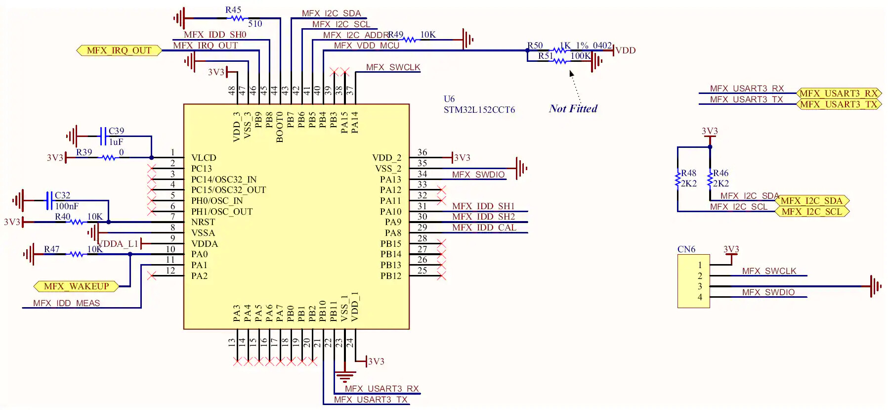
The MFX is simply an STM32L152 chip loaded with firmware allowing it to act as a touch screen driver, I/O expander, and IDD controller. Only the last of these functions is taken advantage of on the STM32L053 Discovery board in order to abstract the above-mentioned current measurement circuitry from the master MCU (the STM32L053C8). Using an I2C bus, the MCU can control the MFX (at address 0x84) by configuring the registers defined in the mfxstm32l152.h file. This file is part of the STM32CubeL0 package and can be found by navigating to en.stm32cubel0/STM32Cube_FW_L0_V1.6.0/Drivers/BSP/Components/mfxstm32l152 . The Excel document provided at the end of this section entitled “MFXSTM32L152_registers.xlsx” is a register map of the MFX common registers and the IDD control registers.
Figure 5 shows the MFX schematic. Notice the net labels that are shared between Figures 5 and 4, which reveal how the MFX interfaces with the resistor network. More importantly, however, are the labels enclosed in hexagons with yellow fill. These are bidirectional ports that are used to interface with other chips on the discovery board. In particular, the MFX_I2C_SDA, MFX_I2C_SCL, MFX_IRQ_OUT, and MFX_WAKEUP ports implement communication between the MFX and the MCU. These ports are connected to pins PB9, PB8, PC13, and PA1 of the STM32L053C8, respectively.
Because no official documentation on the MFX is available, the demo application for the STM32L053 Discovery board had to be studied in order to determine the correct the initialization procedure. This demo application was also found in the STM32CubeL0 folder, and the specific files used for current measurement were found in the en.stm32cubel0/STM32Cube_FW_L0_V1.6.0/Projects/STM32L053C8-Discovery/Demonstrations/Modules/iddmeasurement directory. From these files, the example function in Listing 1 was written on order to demonstrate how the MFX should be initialized to properly control the shunt resistors and send an interrupt signal to the MCU. The basic procedure is outlined as follows:
- A software reset is performed on the MFX to place it into a known state. A delay of 100 ms is placed immediately after this action in order to give the MFX registers time to be cleared.
- The IRQ_OUT signal is configured to inform the MCU that an MFX event has occurred. First, the physical pin on the MFX chip is configured as push-pull, active high (meaning that when an event occurs, the MFX_IRQ_OUT pin state will change from low to high). Then, the events which trigger the IRQ_OUT signal are selected. In this example, the “IDD” and “ERROR” events are chosen, i.e. the IRQ_OUT pin will be set either when an IDD measurement is ready or when any error occurs within the MFX. Notice that at the beginning of the
Idd_Init()function, pin PC13 on the MCU is configured to trigger an interrupt on a rising edge. - The IDD measurement function is enabled on the MFX
- The current measurement parameters are assigned to the MFX. These include the values of the current sense resistors and the gain of the differential amplifier. Also assigned is the minimum voltage (VDD) that may be applied to the MFX before a reset will occur. Since the registers that contain these values are located sequentially in memory (addresses 0x82 to 0x8F), the example function fills an array with the values to be written and then writes all 14 values to the block of memory at once.
Listing 1: Example of initializing the MFX for IDD measurements
void Idd_Init( void )
{
    uint8_t params[14];

    /* Initialize GPIOs */
    // PC13: recieve MFX_IRQ_OUT signal
    RCC->IOPENR |= RCC_IOPENR_GPIOCEN; // enable clocks
    RCC->APB2ENR |= RCC_APB2ENR_SYSCFGEN; // ENABLE SYSTEM CONFIGURATION CONTROLLER CLOCK
    GPIOC->MODER &= ~( GPIO_MODER_MODE13 ); // Input mode
    // Configure external interrupt on MFX_IRQ_OUT (PC13)
    SYSCFG->EXTICR[3] |= SYSCFG_EXTICR4_EXTI13_PC; // PC13 is source for EXTI
    EXTI->IMR |= EXTI_IMR_IM13; // interrupt request from line 13 masked
    EXTI->RTSR |= EXTI_RTSR_TR13; // rising trigger enabled for input line 13

    // NOTE: I2C pins are configured in I2C_init function
    /* Initialize MFX */
    // reset MFX ( SYS_CTRL = SWRST )
    params[0] = 0x80;
    I2C_Write_Reg( I2C1, 0x84, 0x40, params, 1 );
    delay_ms( 100 );  // Give the registers time to be reset
    // IRQ pin -> push-pull, active high
    // ( IRQ_OUT = OUT_PIN_TYPE_PUSHPULL | OUT_PIN_POLARITY_HIGH )
    params[0] = 0x03;
    I2C_Write_Reg( I2C1, 0x84, 0x41, params, 1 );
    delay_ms( 1 );
    // IRQ source -> error and IDD ( IRQ_SRC_EN = IRQ_ERROR | IRQ_IDD )
    params[0] = 0x06;
    I2C_Write_Reg( I2C1, 0x84, 0x42, params, 1 );
    // Enable IDD function ( SYS_CTRL = IDD_EN )
    params[0] = 0x04;
    I2C_Write_Reg( I2C1, 0x84, 0x40, params, 1 );
    // Assign shunt values, gain value, and min VDD value
    params[0] = 0x03; params[1] = 0xE8;        // SH0 = 1000 mohm
    params[2] = 0x00; params[3] = 0x18;        // SH1 = 24 ohm
    params[4] = 0x02; params[5] = 0x6C;     // SH2 = 620 ohm
    params[6] = 0x00; params[7] = 0x00;        // SH3 = not included
    params[8] = 0x27; params[9] = 0x10;     // SH4 = 10,000 ohm
    params[10] = 0x13; params[11] = 0x7E; // Gain = 49.9 (4990)
    params[12] = 0x0B; params[13] = 0xB8;    // VDD_MIN = 3000 mV
    I2C_Write_Reg( I2C1, 0x84, 0x82, params, 14 );
    /* enable interrupts for external interrupt lines 4 - 15 */
    EXTI->PR |= EXTI_PR_PR13; // clear pending interrupt (if it is pending)
    NVIC_EnableIRQ( EXTI4_15_IRQn );
    NVIC_SetPriority( EXTI4_15_IRQn, IDD_INT_PRIO );
}
Once the MFX is initialized, IDD measurements can be requested. Listing 2 is an example of how to do just that. The first step is to specify a pre-delay (if desired). This is the amount of time that will elapse before the measurement is taken. Setting the most significant bit in the IDD_PRE_DELAY register will cause the pre-delay value to be interpreted in units of 20 ms, whereas clearing it changes the units to 5 ms. Then, the measurement is requested by setting the IDD_CTRL_REQ bit and the IDD_CTRL_SHUNT_NB bits in the IDD_CTRL register (see the Excel document). Since there are four shunt resistors on the Discovery board, 0x04 is written to the IDD_CTRL_SHUNT_NB field.
Listing 2: Example of requesting an IDD measurement from the MFX
void Idd_req_meas( uint8_t predelay )
{
uint8_t param;
predelay |= 0x80; // IDD_PRE_DELAY |= IDD_PREDELAY_20_MS
I2C_Write_Reg( I2C1, 0x84, 0x81, &predelay, 1 ); //add predelay before Idd measurement
param = 0x09; // IDD_CTRL = ( ( 4 << 1 ) & IDD_CTRL_SHUNT_NB ) | IDD_CTRL_REQ
I2C_Write_Reg( I2C1, 0x84, 0x80, ¶m, 1 ); // request Idd measurement
}
Once the measurement is ready, it can be read from the three IDD_VALUE registers, as shown in Listing 3. However, the IRQ_PENDING register should be first be read in order to see if the IRQ_ERROR bit is set. If it is, the MFX may not respond when attempting to read the IDD measurement value. If there is no error, the IDD value can be read from memory addresses 0x14 (IDD_VALUE_MSB) to 0x16 (IDD_VALUE_LSB). Then, an acknowledgment must be sent to the MFX by setting the IRQ_IDD bit in the IRQ_ACK register in order to let the MFX know that the interrupt was received and handled. Note that once all three bytes of the IDD value are combined, the result will be in units of 10nA. In order to convert the value to nA, simply multiply it by 10.
Listing 3: Example of reading an IDD measurement from the MFX
int Idd_get_meas( void )
{
    uint8_t temp[3];
    uint8_t ack;

    // check for errors
    I2C_Read_Reg( I2C1, 0x84, 0x08, temp, 1 );
    if ( temp[0] & 0x04 ) // if ( REG_IRQ_PENGDING & IRQ_ERROR )
    {
        Idd_Init();
        CURR_MEAS_POS();  // move cursor to current measurement position
        USART_puts( USART1, "MFX ERROR" );
        return -1;
    }

    I2C_Read_Reg( I2C1, 0x84, 0x14, temp, 3 ); // read current measurement
    ack = 0x02;
    I2C_Write_Reg( I2C1, 0x84, 0x44, &ack, 1 ); // acknowledge Idd from MFX
    return (temp[0]<<16) + (temp[1]<<8) + temp[2];
}
Register Map
As mentioned above, an Excel spreadsheet documenting the registers relevant to this discussion is included below. The definitions in the mfxstm32l152.h file were complied in order to fill in the address and bit columns. Likewise, any useful comments were placed in the comments and permissions columns. The reset value column was determined by running a test that read every register immediately after a software reset. There are many blank cells because some registers were not commented very well (or at all) and some bit fields were not defined. Still, this spreadsheet is a useful reference for who would like to understand what the seemingly random hexadecimal numbers used in the example functions above actually represent.
- MFXSTM32L152_registers.zip (13.5 KB)
Example Application
The demonstration program that comes pre-loaded on the STM32L053 Discovery kit will allow the user to chose between four modes of operation via the touch sensor and the current consumed will be displayed on the E-paper display. These modes include, Run mode, Sleep mode, Low-power sleep mode, and Stop mode. In order to further emphasize the low-power capabilities of the STM32L053 device while avoiding the clutter of ST’s Hardware Abstraction Libraries, a new application was written that uses fewer peripherals and board features. This new example application includes the two low-power modes that were excluded from the demo application (Low-power run mode and Standby mode) and takes continuous measurements at a rate of about one measurement per second.
A terminal emulator provides the user interface for the application. Figure 6 is a screen shot of the output. The current measurement is displayed in the top window and the modes of operation are listed in the bottom window. An arrow points to the current mode and instructions for choosing a different mode are shown at the very bottom. Any terminal emulator program (e.g. PuTTY, Tera Term, CoolTerm, etc.) should work as long as the baud rate is set to 4800 and there is an implicit carriage return (CR) in every line feed (LF). If the sticker on the back of the STM32L053 Discovery board is labeled “MB1143 B-01” or later, then solder bridges SB2 and SB3 will need to be closed so the USART can interface with the virtual COM port (Section 4.14 of the Discovery board user manual).

At the heart of the application is a Finite State Machine (FSM), where each state corresponds to one of the six modes of operation. The entry action for each is these states are functions that will configure the system clocks, power control registers, and the M0+ core registers in order to place the device into the desired mode of operation. These function are each named enter_<Mode>() , where <Mode> is replaced by one of the following: Run , LPRun , Sleep , LPSleep , Stop , or Standby . More information on these functions and their corresponding low-power modes can be found on the Low-Power Modes on the STM32L0 Series page.
Aside from the FSM, there is a background thread that will handle the current measurement functionality. It executes every time the MFX sets the IRQ_OUT line to signal that the current measurement is ready (recall that PC13 on the MCU is used to trigger an external interrupt). This thread uses the procedures discussed in the previous section to get the current measurement, display it, and request a new measurement. In order to verify the correctness of the current measurements delivered by the IDD measurement module, a digital multimeter was used for comparison. Three measurements for each mode using both methods were taken and the averages were reported in Table 1. In order to use the multimeter to take stable measurements, the the MFX was not initialized. This prevented the background thread from running and causing the MCU to temporarily enter Run mode every second. As the results show, the IDD module is not the most accurate of methods for Run mode, Sleep mode, and Low-power sleep mode, but is still impressively close considering the simplicity of the circuitry.
Table 1: Comparison of the measurements of current consumed by the MCU in various operating modes
| Mode | IDD Module | Multimeter |
|---|---|---|
| Run | 3.399 mA | 3.451 mA |
| LPRun | 44.052 µA | 44.063 µA |
| Sleep | 1.331 mA | 1.474 mA |
| LPSleep | 14.179 µA | 15.233 µA |
| Stop | 451 nA | 443 nA |
| Standby | 297 nA | 288 nA |
Complete Example Code
Because this is a relatively simple application that does not utilize ST’s Hardware Abstraction Libraries, all of the code was placed in the main.c file (provided below in Listing 4). Written using Keil’s µVision5 IDE, it is heavily commented and (hopefully) organized in a very logical manner. For those new to Keil’s development tools, the procedure for creating this application from scratch is outlined below.
- Open µVision5 and go to Project > Manage > Pack Installer…
- In the left window, choose the device (STMicroelectronics > STM32L0 Series > STM32L053 > STM32L053C8 > STM32L053C8Tx)
- In the right window, click the Install buttons next to “Keil::STM32L0xx_DFP” and “ARM::CMSIS”
- Close the Pack Installer window and go to Project > New µVision Project…
- Navigate to the folder that will contain the project, enter a name for the project (e.g. STM32L035-DISCO_current_meas), and click Save
- Select the device (in the bottom left box, navigate to STMicroelectronics > STM32L0 Series > STM32L053 > STM32L053C8 > STM32L053C8Tx) and click OK
- Expand the “CMSIS” software component and check the box across from “Core”
- Select “Standalone” from the drop-down menu across from the “Device” software component. Expand the “Device” software component and check the box across from “Startup”. Click OK
- In the Project menu, expand “Target 1”, right-click on “Source Group 1”, and select Add Existing Files to Group ‘Source Group 1’…
- Navigate to wherever main.c is stored, select it, click Add, and then click Close
- Go to Project > Options for Target ‘Target 1’… (Note: you may have to open and close Options for Group ‘Source Group 1’… in order for this option to appear)
- Under the Debug tab, choose ST-Link Debugger from the top right drop-down menu
- Next to that drop-down menu, click Settings, go to the Flash Download tab, click the only option for Programming Algorithms (STM32L0 64KB Flash), and click OK
- Click OK again, and go to Project > Build Target
- Finally, go to Flash > Download (once the download is complete, the reset button may have to be pressed to use the application)
If all goes well, the board should be programmed and ready to use. Simply open a terminal emulator, set the baud rate to 4800, and open the correct COM port. Note that some terminal emulators will not print a carriage return automatically when a line feed is received, so that setting will have to be changed if necessary.
Listing 4: main.c
/*******************************************************************************
*
* Program: Current Meas. (rev2)
*
* Author: Matt Mielke
*
* Company: Digi-Key Electronics
*
* Date: September 21, 2016
*
* Description: This program provides an example of interfacing with the MFX
* in order to provide current measurements for each sleep mode
* offered by the STM32L053C8.
*
* Modifications:
* Date Comment
*---------- ------------------------------------------------------------------
*
*
*******************************************************************************/
/******************************************************************************/
/* Includes */
/******************************************************************************/
#include "stm32l0xx.h"
#include <stdio.h>
/******************************************************************************/
/* Defines */
/******************************************************************************/
// System clocks
#define SYSCLK_FREQ ( SystemCoreClock )
#define AHB_PRESC 1
#define HCLK_FREQ ( SYSCLK_FREQ / AHB_PRESC )
#define APB1_PRESC 1
#define PCLK1_FREQ ( HCLK_FREQ / APB1_PRESC )
#define APB2_PRESC 1
#define PCLK2_FREQ ( HCLK_FREQ / APB2_PRESC )
#define USART1CLK_FREQ PCLK2_FREQ
#define I2C1CLK_FREQ PCLK1_FREQ
// USART
#define U1_BAUD_RATE 4800
#define TERM_USART USART1 // USART periph. that interfaces with terminal
// Finite State Machine (FSM)
#define NUM_STATES 6
#define RUN &fsm[0]
#define LPRUN &fsm[1]
#define SLEEP &fsm[2]
#define LPSLEEP &fsm[3]
#define STOP &fsm[4]
#define STANDBY &fsm[5]
// Interrupts
#define IDD_INT_PRIO 3
#define BTN_INT_PRIO 3
#define USART_INT_PRIO 0
// ANSI Escape Sequences
#define CLEAR_TERMINAL() USART_puts( TERM_USART, "\x1B" "[2J" )
#define CURSOR_HOME() USART_puts( TERM_USART, "\x1B" "[H" )
#define CURSOR_OFF() USART_puts( TERM_USART, "\x1B" "[?25l" )
#define CURSOR_BACK() USART_puts( TERM_USART, "\x1B" "[1D" )
#define SAVE_CURSOR_POS() USART_puts( TERM_USART, "\x1B" "7" )
#define RESTORE_CURSOR_POS() USART_puts( TERM_USART, "\x1B" "8" )
// Application Specific Escape Sequences
#define CURR_MEAS_POS() USART_puts( TERM_USART, "\x1B" "[4;10H" )
#define DEBUG_POS() USART_puts( TERM_USART, "\x1b" "[4;30H" )
#define MESSASAGE_POS() USART_puts( TERM_USART, "\x1B" "[16;3H" )
#define PRINT_UI() USART_puts( TERM_USART, \
" ______________________ \n" \
" | Current Consumption: |\n" \
" |----------------------|\n" \
" | |\n" \
" |______________________|\n" \
" ______________________ \n" \
" | Mode |\n" \
" |----------------------|\n" \
" | 0: Run |\n" \
" | 1: Low-Power Run |\n" \
" | 2: Sleep |\n" \
" | 3: Low-Power Sleep |\n" \
" | 4: Stop |\n" \
" | 5: Standby |\n" \
" |______________________|\n" )
/******************************************************************************/
/* Structures and Enumerations */
/******************************************************************************/
// Each state contains an entry action and an array of pointers to the next
// state corresponding to each possible input.
typedef const struct State
{
void (*entry_action)( void );
const struct State* next[NUM_STATES];
}State_Type;
/******************************************************************************/
/* Function Prototypes */
/******************************************************************************/
void Config_SysClk_HSI16( void );
void Config_SysClk_MSI_131( void );
void delay_ms( int t_ms );
void enter_Run( void );
void enter_LPRun( void );
void enter_Sleep( void );
void enter_LPSleep( void );
void enter_Stop( void );
void enter_Standby( void );
void I2C1_Init( void );
void I2C_Read_Reg( I2C_TypeDef* pI2C, uint16_t dev_addr, uint8_t reg, uint8_t* data, uint8_t count );
void I2C_Write_Reg( I2C_TypeDef* pI2C, uint16_t dev_addr, uint8_t reg, uint8_t* data, uint8_t count );
void Idd_Init( void );
int Idd_get_meas( void );
void Idd_report_meas( int meas );
void Idd_req_meas( uint8_t predelay );
void Idd_RestoreContext(void);
void Idd_SaveContext(void);
void SysTick_Init( double overflow_period );
void USART1_Init( void );
char USART_getc( USART_TypeDef* pUSART );
void USART_putc( USART_TypeDef* pUSART, char character );
void USART_puts( USART_TypeDef* pUSART, char* str );
/******************************************************************************/
/* Global Variables */
/******************************************************************************/
uint8_t user_input = 0; // input to FSM
// the context of the gpio modes are saves in these variables
uint32_t GPIOA_MODER = 0, GPIOB_MODER = 0, GPIOC_MODER = 0;
State_Type fsm[NUM_STATES] = // the FSM
{// entry_action //next state
{ enter_Run, { NULL, LPRUN, SLEEP, LPSLEEP, STOP, STANDBY } },
{ enter_LPRun, { RUN, NULL, RUN, LPSLEEP, RUN, RUN } },
{ enter_Sleep, { RUN, LPRUN, SLEEP, LPSLEEP, STOP, RUN } },
{ enter_LPSleep, { RUN, LPRUN, RUN, LPSLEEP, RUN, RUN } },
{ enter_Stop, { RUN, LPRUN, SLEEP, LPSLEEP, STOP, STANDBY } },
{ enter_Standby, { RUN, LPRUN, SLEEP, LPSLEEP, STOP, STANDBY } },
};
State_Type* curr_state = RUN; // store current state of program
// ANSI escape sequences
const char ModePosition[6][8] = { // position of '>' for each mode
{ "\x1B" "[9;3H" },
{ "\x1B" "[10;3H" },
{ "\x1B" "[11;3H" },
{ "\x1B" "[12;3H" },
{ "\x1B" "[13;3H" },
{ "\x1B" "[14;3H" }, };
/******************************************************************************/
/* Interrupt Service Routines */
/******************************************************************************/
/* Entered if data is recieved from USART1 */
void USART1_IRQHandler( void )
{
if ( USART1->ISR & USART_ISR_RXNE ) // Data was received
{
// NOTE: flag cleared by reading USART1->RDR
user_input = ( USART_getc( USART1 ) & 0xF );
if ( user_input >= NUM_STATES )
{
user_input = NUM_STATES - 1;
}
SCB->SCR &= ~( SCB_SCR_SLEEPONEXIT_Msk ); // go to FSM control loop
}
}
/* Entered if user button is pressed in Stop mode (and only Stop mode) */
void EXTI0_1_IRQHandler( void )
{
if ( EXTI->PR & EXTI_PR_PR0 ) // User button pressed
{
EXTI->PR |= EXTI_PR_PR0; // Acknowledge interrupt
user_input = 0; // enter the RUN state
// disable this external interrupt
EXTI->IMR &= ~( EXTI_IMR_IM0 );
NVIC_DisableIRQ( EXTI0_1_IRQn );
}
}
/* Entered when Idd measurement is ready */
// not recognized by the FSM (it is a background thread)
// (must be entered by software when waking from Standby mode)
void EXTI4_15_IRQHandler( void )
{
if ( EXTI->PR & EXTI_PR_PR13 ) // Idd measurement ready
{
EXTI->PR |= EXTI_PR_PR13; // Acknowledge interrupt
Idd_report_meas( Idd_get_meas() );
Idd_req_meas( 50 ); // 1 second
// ensure USART transmission completes before stopping the peripheral
while ( !( USART1->ISR & USART_ISR_TC ) );
}
}
/*******************************************************************************
* Function: main
* Author: Matt Mielke
* Desctription: This is entry point for the program. As always, SystemInit()
* is called to ensure the system is in a known state. The
* enter_Run funciton will initialize the system frequency and the
* peripherals dependent on that frequency. Then, Idd_Init() will
* initialize the MFX to take current measurements and interrupt
* execution when the measurement is ready.
* Since Standby mode is used in this application (and it
* essentially resets the device) the SBF flag must be checked once
* the system is up and running. If the device was woken up from
* Standby mode, the state of the user button must be checked to
* determine what triggered the wake-up event. If the user button
* is depressed, the user woke the device wanting to re-enter Run
* mode. The the user button is not depressed, the MFX woke the
* device wanting to report a current measurement.
* If the program is executing for the first time, the terminal
* is cleared and the GUI is redrawn. In order to avoid having to
* store the previous state, the terminal can save the last
* position of the '>' character so it can be returned to, cleared,
* and redrawn in the current position. The user interface is
* updated each time the FSM control loop is entered.
* Other than update the user interface, the FSM control loop
* simply uses the user input to change the state of the program.
* These state transistions are defined by the fsm structure above.
* Date: 09-21-16
*******************************************************************************/
int main(void)
{
SystemInit();
enter_Run(); // start program in the running state
/* If we woke up from Standby mode, restore FSM */
if ( PWR->CSR & PWR_CSR_SBF ) // Did we wakeup from standby mode?
{
PWR->CR |= PWR_CR_CSBF; // clear the Standby flag
RCC->IOPENR |= RCC_IOPENR_GPIOAEN; // port A clock enabled
GPIOA->MODER &= ~( GPIO_MODER_MODE0 ); // PA0 in input mode
if ( GPIOA->IDR & GPIO_IDR_ID0 ) // if user button (PA0) is being pressed
{
curr_state = STANDBY;
PWR->CSR &= ~( PWR_CSR_EWUP1 | PWR_CSR_EWUP2 ); // disable wake-up pins
Idd_Init();
Idd_req_meas( 50 ); // request initial measurement (1 second)
}
else // MFX caused wake up, so print current meas. and re-enter Standy mode
{
/* Enable external interrupt 13 */
EXTI->IMR |= EXTI_IMR_IM13; // interrupt request from line 13 masked
EXTI->PR |= EXTI_PR_PR13; // clear pending interrupt (if it is pending)
NVIC_EnableIRQ( EXTI4_15_IRQn );
user_input = 5;
EXTI->SWIER |= EXTI_SWIER_SWI13; // trigger Idd meas. ready interrupt
}
}
/* If this is the first execution, initialize FSM */
else
{
CURSOR_OFF();
CLEAR_TERMINAL();
CURSOR_HOME();
PRINT_UI();
USART_puts( USART1, (char*)ModePosition[user_input] );
USART_putc( USART1, '>' );
SAVE_CURSOR_POS();
MESSASAGE_POS();
USART_puts( USART1, "Press keys 0 - 5 to \n change the power mode " );
Idd_Init();
Idd_req_meas( 50 ); // request initial measurement (1 second)
}
// FSM and GUI control loop
while( 1 )
{
if ( curr_state->next[user_input] != NULL )
{
__disable_irq(); // no interrupts may use the USART right now...
// update position of arrow ('>')
RESTORE_CURSOR_POS();
CURSOR_BACK(); // move cursor back one space
USART_putc( USART1, ' ' ); // overwrite '>'
USART_puts( USART1, (char*)ModePosition[user_input] );
USART_putc( USART1, '>' );
SAVE_CURSOR_POS();
// update state
curr_state = curr_state->next[user_input];
// update instructions for changing state
MESSASAGE_POS(); // move cursor to message position
if ( curr_state == STOP )
{
USART_puts( USART1, "Press the user button \n to enter run mode " );
}
else if ( curr_state == STANDBY )
{
USART_puts( USART1, "Press and hold the user\n button to enter run mode" );
}
else
{
USART_puts( USART1, "Press keys 0 - 5 to \n change the power mode " );
}
// wait for USART transmission to complete
while ( !( USART1->ISR & USART_ISR_TC ) );
__enable_irq(); // ...interrupts may use the USART again
// perform entry action of the new state
curr_state->entry_action();
}
}
return 0; // we should never get here
}
/*******************************************************************************
* Function: Config_SysClk_HSI16
* Author: Matt Mielke
* Desctription: This function will configure the system clock to run at 16 MHz
* using the High Speed Internal 16 MHz oscillator. All other
* oscillators are disabled and the SystemCoreClock global variable
* is update using the SystemCoreClockUpdate() function.
* Date: 09-22-16
*******************************************************************************/
void Config_SysClk_HSI16( void )
{
/* Enable Clock */
RCC->CR |= RCC_CR_HSION; // HSI16 oscillator ON
while ( !( RCC->CR & RCC_CR_HSIRDY ) ); // wait until HSI16 is ready
/* Switch System Clock */
// HSI16 oscillator used as system clock
RCC->CFGR = ( RCC->CFGR & ~RCC_CFGR_SW ) | RCC_CFGR_SW_HSI;
while ( ( RCC->CFGR & RCC_CFGR_SWS ) != RCC_CFGR_SWS_HSI ); // wait until switched
/* Disable other clocks (excluding LSE and LSI) */
RCC->CR &= ~( RCC_CR_MSION | RCC_CR_HSEON | RCC_CR_PLLON );
SystemCoreClockUpdate();
}
/*******************************************************************************
* Function: Config_SysClk_MSI_131
* Author: Matt Mielke
* Desctription: This function will configure the system clock to run at
* 131,072 Hz using the Multi-Speed Internal oscillator. All other
* oscillators are disabled and the SystemCoreClock global variable
* is update using the SystemCoreClockUpdate() function.
* Date: 09-22-16
*******************************************************************************/
void Config_SysClk_MSI_131( void )
{
/* Enable and Configure Clock */
RCC->CR |= RCC_CR_MSION;
RCC->ICSCR = ( RCC->ICSCR & ~RCC_ICSCR_MSIRANGE ) | RCC_ICSCR_MSIRANGE_1;
while ( !( RCC->CR & RCC_CR_MSIRDY ) ); // wait until MSI is ready
/* Switch System Clock */
// MSI oscillator used as system clock
RCC->CFGR = ( RCC->CFGR & ~RCC_CFGR_SW ) | RCC_CFGR_SW_MSI;
while ( ( RCC->CFGR & RCC_CFGR_SWS ) != RCC_CFGR_SWS_MSI ); // wait unit switched
/* Disable other clocks (excluding LSE and LSI) */
RCC->CR &= ~( RCC_CR_HSION | RCC_CR_HSEON | RCC_CR_PLLON );
SystemCoreClockUpdate();
}
/*******************************************************************************
* Function: delay_ms
* Author: Matt Mielke
* Desctription: This function assumes the SysTick peripheral is configured to
* underflow every ms. It simply does nothing for t_ms underflows
* in order to delay t_ms milliseconds.
* Date: 09-12-16
*******************************************************************************/
void delay_ms( int t_ms )
{
SysTick->VAL = 0;
while ( t_ms > 0 )
{
while ( !( SysTick->CTRL & SysTick_CTRL_COUNTFLAG_Msk ) ); // wait for underflow
t_ms--;
}
}
/*******************************************************************************
* Function: enter_Run
* Author: Matt Mielke
* Desctription: This function configures the device for run mode. To avoid
* problems entering the low-power modes, the regulator
* configuration is reset right away. Then, the system frequency
* is set to 16MHz and the peripherals dependent on it are
* initialized.
* Date: 09-21-16
*******************************************************************************/
void enter_Run( void )
{
/* Enable Clocks */
RCC->APB1ENR |= RCC_APB1ENR_PWREN;
/* Force the regulator into main mode */
// Reset LPRUN bit
PWR->CR &= ~( PWR_CR_LPRUN );
// LPSDSR can be reset only when LPRUN bit = 0;
PWR->CR &= ~( PWR_CR_LPSDSR );
/* Set HSI16 oscillator as system clock */
Config_SysClk_HSI16();
// Reinitialize peripherals dependent on clock speed
USART1_Init();
SysTick_Init( 0.001 );
I2C1_Init();
}
/*******************************************************************************
* Function: enter_LPRun
* Author: Matt Mielke
* Desctription: This function will configure the system for Low-power run
* mode and enter is using the procedure outlined on page __ of
* reference manual. After enabling/disabling the desired clocks,
* the system frequency is set to 131 kHz. It could be lower than
* this, but serial communication would become more difficult (or
* even impossible). The frequency dependent peripherals are then
* re-initialized and the regulator is forced into low-power mode.
* Date: 09-21-16
*******************************************************************************/
void enter_LPRun( void )
{
/* 1. Each digital IP clock must be enabled or disabled by using the
RCC_APBxENR and RCC_AHBENR registers */
RCC->APB1ENR |= RCC_APB1ENR_PWREN;
/* 2. The frequency of the system clock must be decreased to not exceed the
frequency of f_MSI range1. */
Config_SysClk_MSI_131();
// Reinitialize peripherals dependent on clock speed
USART1_Init();
SysTick_Init( 0.001 );
I2C1_Init();
/* 3. The regulator is forced in low-power mode by software
(LPRUN and LPSDSR bits set ) */
PWR->CR &= ~PWR_CR_LPRUN; // Be sure LPRUN is cleared!
PWR->CR |= PWR_CR_LPSDSR; // must be set before LPRUN
PWR->CR |= PWR_CR_LPRUN; // enter low power run mode
}
/*******************************************************************************
* Function: enter_Sleep
* Author: Matt Mielke
* Desctription: This function will enter Sleep mode by properly configuring
* the SLEEPDEEP bit in the SCR. The SLEEPONEXIT bit is also set as
* the device will only need to be awake to service interrups.
* Also, the Flash is not disabled in order to minimize wake-up
* latency. Sleep mode is entered with the WFI instruction.
* Date: 09-22-16
*******************************************************************************/
void enter_Sleep( void )
{
/* Configure low-power mode */
SCB->SCR &= ~( SCB_SCR_SLEEPDEEP_Msk ); // low-power mode = sleep mode
SCB->SCR |= SCB_SCR_SLEEPONEXIT_Msk; // reenter low-power mode after ISR
/* Ensure Flash memory stays on */
FLASH->ACR &= ~FLASH_ACR_SLEEP_PD;
__WFI(); // enter low-power mode
}
/*******************************************************************************
* Function: enter_LPSleep
* Author: Matt Mielke
* Desctription: This function will put the device in Low-power sleep mode
* by following the procedure described on page __ of the
* reference manual. Power consumption is minimized by disabling
* the Flash and in order to get the regulator into low-power mode,
* the system frequency is decreased to 131 kHz. The necessary
* peripherals are re-initialized and Low-power sleep mode is
* entered through the WFI instuction.
* Date: 09-22-16
*******************************************************************************/
void enter_LPSleep( void )
{
/* 1. The Flash memory can be switched off by using the control bits
(SLEEP_PD in the FLASH_ACR register). This reduces power consumption
but increases the wake-up time. */
FLASH->ACR |= FLASH_ACR_SLEEP_PD;
/* 2. Each digital IP clock must be enabled or disabled by using the
RCC_APBxENR and RCC_AHBENR registers */
RCC->APB1ENR |= RCC_APB1ENR_PWREN;
/* 3. The frequency of the system clock must be decreased to not exceed the
frequency of f_MSI range1. */
// Set MSI 131.072 kHz as system clock
Config_SysClk_MSI_131();
// Reinitialize peripherals dependent on clock speed
USART1_Init();
SysTick_Init( 0.001 );
I2C1_Init();
/* 4. The regulator is forced in low-power mode by software
(LPSDSR bits set ) */
PWR->CR |= PWR_CR_LPSDSR; // voltage regulator in low-power mode during sleep
/* 5. Follow the steps described in Section 6.3.5: Entering low-power mode */
SCB->SCR &= ~( SCB_SCR_SLEEPDEEP_Msk ); // low-power mode = sleep mode
SCB->SCR |= SCB_SCR_SLEEPONEXIT_Msk; // reenter low-power mode after ISR
__WFI(); // enter low-power mode
}
/*******************************************************************************
* Function: enter_Stop
* Author: Matt Mielke
* Desctription: This function will not only configure and enter Stop mode,
* but also configure an external interrupt connected to PA0 (the
* user button) in order to wake the device. In order to use less
* power, V_{REFINT} is disabled, the regulator is placed in
* low-power mode, and the I/O pins are placed in analog mode. Stop
* mode is entered using the WFI instruction and once the device is
* woken, the system is restored to a working state before the
* external interrupt ISR is entered.
* Date: 09-23-16
*******************************************************************************/
void enter_Stop( void )
{
/* Enable Clocks */
RCC->APB1ENR |= RCC_APB1ENR_PWREN;
RCC->IOPENR |= RCC_IOPENR_GPIOAEN;
/* Configure PA0 as External Interrupt */
GPIOA->MODER &= ~( GPIO_MODER_MODE0 ); // PA0 is in Input mode
EXTI->IMR |= EXTI_IMR_IM0; // interrupt request from line 0 not masked
EXTI->RTSR |= EXTI_RTSR_TR0; // rising trigger enabled for input line 0
// Enable interrupt in the NVIC
NVIC_EnableIRQ( EXTI0_1_IRQn );
NVIC_SetPriority( EXTI0_1_IRQn, BTN_INT_PRIO );
/* Prepare to enter stop mode */
PWR->CR |= PWR_CR_CWUF; // clear the WUF flag after 2 clock cycles
PWR->CR &= ~( PWR_CR_PDDS ); // Enter stop mode when the CPU enters deepsleep
// V_REFINT startup time ignored | V_REFINT off in LP mode | regulator in LP mode
PWR->CR |= PWR_CR_FWU | PWR_CR_ULP | PWR_CR_LPSDSR;
RCC->CFGR |= RCC_CFGR_STOPWUCK; // HSI16 oscillator is wake-up from stop clock
SCB->SCR |= SCB_SCR_SLEEPDEEP_Msk; // low-power mode = stop mode
__disable_irq();
Idd_SaveContext();
I2C1->CR1 &= ~I2C_CR1_PE; // Address issue 2.5.1 in Errata
__WFI(); // enter low-power mode
I2C1->CR1 |= I2C_CR1_PE;
Idd_RestoreContext();
__enable_irq(); // <-- go to isr
}
/*******************************************************************************
* Function: enter_Standby
* Author: Matt Mielke
* Desctription: This function will enter Standby mode and enable the devices
* two wake-up pins (PA0 and PC13). This way, either the user
* button or a signal from the MFX can wake the device.
* Date: 09-27-16
*******************************************************************************/
void enter_Standby( void )
{
/* Enable Clocks */
RCC->APB1ENR |= RCC_APB1ENR_PWREN;
/* Prepare for Standby */
// if WKUP pins are already high, the WUF bit will be set
PWR->CSR |= PWR_CSR_EWUP1 | PWR_CSR_EWUP2;
PWR->CR |= PWR_CR_CWUF; // clear the WUF flag after 2 clock cycles
PWR->CR |= PWR_CR_ULP; // V{REFINT} is off in low-power mode
PWR->CR |= PWR_CR_PDDS; // Enter Standby mode when the CPU enters deepsleep
SCB->SCR |= SCB_SCR_SLEEPDEEP_Msk; // low-power mode = stop mode
__WFI(); // enter low-power mode
}
/*******************************************************************************
* Function: I2C1_Init
* Author: Matt Mielke
* Desctription: Pins PB8 and PB9 are configured as the I2C1_SCL and I2C_SDA
* pins, respectively. The timing register of the I2C1 peripheral
* is configured to work across a frequency range of 131072 Hz to
* 32 MHz. This is accomplished by setting the SCLH and SCLL
* bitfields to 5 (as this provides a minumum f_{SCL} of about
* 10 kHz, and setting the SCLDEL and SDADEL bitfields to 0. Note
* that the value of SDADEL is of little concern because
* NOSTRETCH = 0. The value of PRESC is dynamically chosen based
* on the frequency of the I2C1 clock. No interrups are enabled as
* the MFX will alert the device when measurements are ready.
* Date: 09-13-16
*******************************************************************************/
void I2C1_Init( void )
{
int presc; // prescaler
/* Enable Clocks */
RCC->APB1ENR |= RCC_APB1ENR_I2C1EN; // Enable I2C1 clock
RCC->IOPENR |= RCC_IOPENR_GPIOBEN; // Enable GPIOB clock
/* Configure GPIOs */
// PB8 = MFX_I2C_SCL -> alternate function mode
// PB9 = MFX_I2C_SDA -> alternate function mode
GPIOB->MODER &= ~( GPIO_MODER_MODE8 | GPIO_MODER_MODE9 );
GPIOB->MODER |= GPIO_MODER_MODE8_1 | GPIO_MODER_MODE9_1;
// AFSEL8 = 4 -> I2C1_SCL // AFSEL9 = 4 -> I2C1_SDA
GPIOB->AFR[1] |= (4 << 0) | (4 << 4);
GPIOB->OTYPER |= GPIO_OTYPER_OT_8 | GPIO_OTYPER_OT_9; // output open drain
/* Configure I2C1 */
I2C1->CR1 &= ~( I2C_CR1_PE ); // ensure I2C1 is disabled
// Try to configure f_SCL = ~150 kHz
// NOTE: NOSTRETCH must equal 0 (default)
// t_{PRESC} = (PRESC+1) x t_{I2CCLK} -> PRESC = f_{I2CCLK}/f_{PRESC} - 1
presc = I2C1CLK_FREQ / 150000 - 1;
presc = presc < 0 ? 0 : presc; // clip presc to 0 if negative
presc = presc > 15 ? 15 : presc; // clip presc to 15 if larger
I2C1->TIMINGR = 0; // clear TIMINGR
// SCLDEL = 0 // SDADEL = 0 // SCLH = 5 // SCLL = 5 // PRESC = presc
I2C1->TIMINGR |= ( (5<<8) & I2C_TIMINGR_SCLH ) | ( 5 & I2C_TIMINGR_SCLL ) |
( ( presc << 28 ) & I2C_TIMINGR_PRESC );
/* Enable I2C1 */
I2C1->CR1 |= I2C_CR1_PE;
}
/*******************************************************************************
* Function: I2C_Read_Reg
* Author: Matt Mielke
* Desctription: This function will read the contents of the slave's memory
* starting at the specified address. The user must specify which
* I2C peripheral to use, the slave address, the address of the
* register to start from, and the number of bytes to be read.
* Also, a buffer for the data to be stored in must be provided.
* Date: 09-13-16
*******************************************************************************/
void I2C_Read_Reg( I2C_TypeDef* pI2C, uint16_t dev_addr, uint8_t reg, uint8_t* data, uint8_t count )
{
uint32_t temp_CR2;
// begin transaction by sending the register address
temp_CR2 = pI2C->CR2;
temp_CR2 &= ~( I2C_CR2_RELOAD | I2C_CR2_NBYTES | I2C_CR2_RD_WRN | I2C_CR2_SADD | I2C_CR2_AUTOEND );
temp_CR2 |= ( dev_addr & I2C_CR2_SADD ) | ( ( 1 << 16 ) & I2C_CR2_NBYTES )
| I2C_CR2_START;
pI2C->CR2 = temp_CR2;
while ( !( pI2C->ISR & I2C_ISR_TXIS ) ); // wait for TXDR to be empty
pI2C->TXDR = reg; // send register address
while ( !( pI2C->ISR & I2C_ISR_TC ) ); // wait for transfer to complete
// continue transaction by reading from slave
temp_CR2 = pI2C->CR2;
temp_CR2 &= ~( I2C_CR2_RELOAD | I2C_CR2_NBYTES | I2C_CR2_SADD );
temp_CR2 |= ( dev_addr & I2C_CR2_SADD ) | ( ( count << 16 ) & I2C_CR2_NBYTES )
| I2C_CR2_RD_WRN | I2C_CR2_AUTOEND | I2C_CR2_START;
pI2C->CR2 = temp_CR2;
do
{
while ( !( pI2C->ISR & I2C_ISR_RXNE ) ); // wait for data to be received
*data = pI2C->RXDR;
data++;
count--;
} while ( count > 0 );
while ( !( pI2C->ISR & I2C_ISR_STOPF ) ); // wait for stop to be detected
pI2C->ICR |= I2C_ICR_STOPCF; // clear the stop detection flag
}
/*******************************************************************************
* Function: I2C_Write_Reg
* Author: Matt Mielke
* Desctription: This function will write to the slave's memory starting at the
* provided starting address. Besides this, the I2C peripheral to
* be used, the slave address, the number of bytes to write,
* and a buffer containing the data to be written must be provided.
* Date: 09-13-16
*******************************************************************************/
void I2C_Write_Reg( I2C_TypeDef* pI2C, uint16_t dev_addr, uint8_t reg, uint8_t* data, uint8_t count )
{
uint32_t temp_CR2;
// begin transaction
temp_CR2 = pI2C->CR2;
temp_CR2 &= ~( I2C_CR2_RELOAD | I2C_CR2_NBYTES | I2C_CR2_RD_WRN | I2C_CR2_SADD );
temp_CR2 |= ( dev_addr & I2C_CR2_SADD ) | ( ( ( count + 1 ) << 16 ) & I2C_CR2_NBYTES )
| I2C_CR2_AUTOEND | I2C_CR2_START;
pI2C->CR2 = temp_CR2;
while ( !( pI2C->ISR & I2C_ISR_TXIS ) ); // wait for TXDR to be empty
pI2C->TXDR = reg; // send register address
// send data
do
{
while ( !( pI2C->ISR & I2C_ISR_TXIS ) ); // wait for TXDR to be empty
pI2C->TXDR = *data;
data++;
count--;
} while ( count > 0 );
while ( !( pI2C->ISR & I2C_ISR_TXE) ); // TXDR is empty and all data has been sent
while ( !( pI2C->ISR & I2C_ISR_STOPF ) ); // wait for stop to be detected
pI2C->ICR |= I2C_ICR_STOPCF; // clear the stop detection flag
}
/*******************************************************************************
* Function: Idd_Init
* Author: Matt Mielke
* Desctription: This function will initialize the MFX based to the hardware
* included on the Discovery board. This includes the number of
* shunts, amplifier gain, and MFX interrupt pin configuration.
* The majority of the initialization was taken from the power.c
* file used in the demo application for this Discovery board. Four
* functions are defined in this file to measuere the current in
* different low power modes, and each of them initializes the MFX
* in the same way.
* NOTE: this function assumes that the I2C lines have already been
* initialized.
* Date: 09-14-16
*******************************************************************************/
void Idd_Init( void )
{
uint8_t params[14];
/* Initialize GPIOs */
// PC13: recieve MFX_IRQ_OUT signal
RCC->IOPENR |= RCC_IOPENR_GPIOCEN; // enable clocks
RCC->APB2ENR |= RCC_APB2ENR_SYSCFGEN; // ENABLE SYSTEM CONFIGURATION CONTROLLER CLOCK
GPIOC->MODER &= ~( GPIO_MODER_MODE13 ); // Input mode
// Configure external interrupt on MFX_IRQ_OUT (PC13)
SYSCFG->EXTICR[3] |= SYSCFG_EXTICR4_EXTI13_PC; // PC13 is source for EXTI
EXTI->IMR |= EXTI_IMR_IM13; // interrupt request from line 13 masked
EXTI->RTSR |= EXTI_RTSR_TR13; // rising trigger enabled for input line 13
// NOTE: I2C pins are configured in I2C_init function
/* Initialize MFX */
// reset MFX ( SYS_CTRL = SWRST )
params[0] = 0x80;
I2C_Write_Reg( I2C1, 0x84, 0x40, params, 1 );
delay_ms( 100 ); // Give the registers time to be reset
// IRQ pin -> push-pull, active high
// ( IRQ_OUT = OUT_PIN_TYPE_PUSHPULL | OUT_PIN_POLARITY_HIGH )
params[0] = 0x03;
I2C_Write_Reg( I2C1, 0x84, 0x41, params, 1 );
delay_ms( 1 );
// IRQ source -> error and IDD ( IRQ_SRC_EN = IRQ_ERROR | IRQ_IDD )
params[0] = 0x06;
I2C_Write_Reg( I2C1, 0x84, 0x42, params, 1 );
// Enable IDD function ( SYS_CTRL = IDD_EN )
params[0] = 0x04;
I2C_Write_Reg( I2C1, 0x84, 0x40, params, 1 );
// Assign shunt values, gain value, and min VDD value
params[0] = 0x03; params[1] = 0xE8; // SH0 = 1000 mohm
params[2] = 0x00; params[3] = 0x18; // SH1 = 24 ohm
params[4] = 0x02; params[5] = 0x6C; // SH2 = 620 ohm
params[6] = 0x00; params[7] = 0x00; // SH3 = not included
params[8] = 0x27; params[9] = 0x10; // SH4 = 10,000 ohm
params[10] = 0x13; params[11] = 0x7E; // Gain = 49.9 (4990)
params[12] = 0x0B; params[13] = 0xB8; // VDD_MIN = 3000 mV
I2C_Write_Reg( I2C1, 0x84, 0x82, params, 14 );
/* enable interrupts for external interrupt lines 4 - 15 */
EXTI->PR |= EXTI_PR_PR13; // clear pending interrupt (if it is pending)
NVIC_EnableIRQ( EXTI4_15_IRQn );
NVIC_SetPriority( EXTI4_15_IRQn, IDD_INT_PRIO );
}
/*******************************************************************************
* Function: Idd_get_meas
* Author: Matt Mielke
* Desctription: Once the MFX signals that a current measurement is ready to be
* read, this function can be called to perform the read operation.
* Before the read is performed, the MFX is checked for errors.
* This is because the same interrupt signal that is used to notify
* the host that a measurement is ready is also used to notify the
* host that an error has occured. If we try to read a current
* measurement when an error has occured, the MFX will not respond
* and the code will hang.
* If an error did in fact occur, then the Idd_Init() function is
* called. This will reset the MFX and re-configure it. An error
* message is then printed rather than the current measurement to
* let the user know that an error occured and has been delt with.
* In order to read the current measurement, the IDD_VALUE_MSB,
* IDD_VALUE_MID, and IDD_VALUE_LSB registers must be read. By
* combining the values in these registers, we will have the
* current being consumed in units of 10nA. After these registers
* are read, an acknowledgment is sent to the MFX so it knows that
* we recieved its interrupt signal and responded to it.
* Date: 09-14-16
*******************************************************************************/
int Idd_get_meas( void )
{
uint8_t temp[3];
uint8_t ack;
// check for errors
I2C_Read_Reg( I2C1, 0x84, 0x08, temp, 1 );
if ( temp[0] & 0x04 ) // if ( REG_IRQ_PENGDING & IRQ_ERROR )
{
Idd_Init();
CURR_MEAS_POS(); // move cursor to current measurement position
USART_puts( USART1, "MFX ERROR" );
return -1;
}
I2C_Read_Reg( I2C1, 0x84, 0x14, temp, 3 ); // read current measurement
ack = 0x02;
I2C_Write_Reg( I2C1, 0x84, 0x44, &ack, 1 ); // acknowledge Idd from MFX
return (temp[0]<<16) + (temp[1]<<8) + temp[2];
}
/*******************************************************************************
* Function: Idd_report_meas
* Author: Matt Mielke
* Desctription: This is an application specific function that will convert the
* current measurement value obtained from the MFX to amps and then
* print it at the predefined position on the terminal. If the
* measurement is negative, it is assumed that the measurement is
* not valid and nothing will be printed.
* Date: 09-14-16
*******************************************************************************/
void Idd_report_meas( int meas )
{
char str[12];
if ( meas < 0 )
{
return;
}
sprintf( (char*)str, "%d.%.3dmA", (int)meas/100000, ((int)meas%100000)/100 );
if ( str[0] == '0' )
{
sprintf( (char*)str, "%d.%.3duA", (int)meas/100, ((int)meas%100)*10 );
if ( str[0] == '0' )
{
sprintf( (char*)str, " %dnA ", (int)meas*10 );
}
}
CURR_MEAS_POS(); // move cursor to current measurement position
USART_puts( USART1, str );
USART_puts( USART1, " " );
}
/*******************************************************************************
* Function: Idd_req_meas
* Author: Matt Mielke
* Desctription: This function will request an Idd measurement from the MFX
* with a predelay in units of 20ms. Once the predelay time has
* elapsed, the MFX will sample the current being drawn and use the
* MFX_IRQ_OUT line to signal the host processor that a measurement
* is ready to be read (assuming the IRQ signal was configured and
* enabled in the Idd initialization function).
* Date: 09-14-16
*******************************************************************************/
void Idd_req_meas( uint8_t predelay )
{
uint8_t param;
predelay |= 0x80; // IDD_PRE_DELAY |= IDD_PREDELAY_20_MS
I2C_Write_Reg( I2C1, 0x84, 0x81, &predelay, 1 ); //add predelay before Idd measurement
param = 0x09; // IDD_CTRL = ( ( 4 << 1 ) & IDD_CTRL_SHUNT_NB ) | IDD_CTRL_REQ
I2C_Write_Reg( I2C1, 0x84, 0x80, ¶m, 1 ); // request Idd measurement
}
/*******************************************************************************
* Function: Idd_RestoreContext
* Author: Matt Mielke
* Desctription: This function uses the following global variables:
* GPIOA_MODER, GPIOB_MODER, and GPIOC_MODER. Assuming the function
* Idd_SaveContext was called before this one, the GPIOx_MODER
* registers will be restored to their original values, taking the
* GPIO pins out of analog mode. Interrupts should not be enabled
* while this function is executing, which is why code is added at
* the beginning and end to disable and reenable interrupts if they
* weren't already disabled when this function was called.
* Date: 09-23-16
*******************************************************************************/
void Idd_RestoreContext(void)
{
char was_waiting = 0;
// disable interrupts if they weren't already disabled
if ( __get_PRIMASK() )
{
was_waiting = 1;
}
else
{
__disable_irq();
}
// Enable GPIO clocks
RCC->IOPENR |= RCC_IOPENR_GPIOAEN | RCC_IOPENR_GPIOBEN | RCC_IOPENR_GPIOCEN;
GPIOA->MODER = GPIOA_MODER; // dummy write
// Restore the previous mode of the I/O pins
GPIOA->MODER = GPIOA_MODER;
GPIOB->MODER = GPIOB_MODER;
GPIOC->MODER = GPIOC_MODER;
// enable interrupts if they were enabled before this function was called
if ( !was_waiting )
{
__enable_irq();
}
}
/*******************************************************************************
* Function: Idd_SaveContext
* Author: Matt Mielke
* Desctription: In this function, the state of the GPIOx_MODER registers are
* save into global variables GPIOA_MODER, GPIOB_MODER, and
* GPIOC_MODER. The MODER registers are all then configured to
* analog mode. This will prevent the GPIO pins from
* consuming any current, not including the external interrupts.
* Interrupts should not be enabled while this function is
* executing which is why code is added at the beginning and end
* to disable and reenable interrupts if they weren't already
* disabled when this function was called.
* Date: 09-23-16
*******************************************************************************/
void Idd_SaveContext(void)
{
char was_waiting = 0;
// disable interrupts if they weren't already disabled
if ( __get_PRIMASK() )
{
was_waiting = 1;
}
else
{
__disable_irq();
}
// Enable GPIO clocks
RCC->IOPENR |= RCC_IOPENR_GPIOAEN | RCC_IOPENR_GPIOBEN | RCC_IOPENR_GPIOCEN;
GPIOA_MODER = GPIOA->MODER; // dummy read
// Save the current mode of the I/O pins
GPIOA_MODER = GPIOA->MODER;
GPIOB_MODER = GPIOB->MODER;
GPIOC_MODER = GPIOC->MODER;
// Configure GPIO port pins in Analog Input mode
GPIOA->MODER = 0xFFFFFFFF;
GPIOB->MODER = 0xFFFFFFFF;
GPIOC->MODER = 0xFFFFFFFF;
// Leave the external interrupts alone!
GPIOC->MODER &= ~( GPIO_MODER_MODE13 ); // Input mode
GPIOA->MODER &= ~( GPIO_MODER_MODE0 );
// Disable GPIO clocks
RCC->IOPENR &= ~( RCC_IOPENR_GPIOAEN | RCC_IOPENR_GPIOBEN | RCC_IOPENR_GPIOCEN );
// enable interrupts if they were enabled before this function was called
if ( !was_waiting )
{
__enable_irq();
}
}
/*******************************************************************************
* Function: SysTick_Init
* Author: Matt Mielke
* Desctription: Initializes the SysTick peripheral to underflow every ms.
* Since it will be used in a busy-wait delay function, interrupts
* are dissabled.
* Date: 09-12-16
*******************************************************************************/
void SysTick_Init( double overflow_period )
{
// counter flag set every <overflow_period> seconds
SysTick_Config( (uint32_t)( (double)SYSCLK_FREQ * overflow_period + 0.5 ) );
SysTick->CTRL &= ~( SysTick_CTRL_TICKINT_Msk ); // no systick interrupt
}
/*******************************************************************************
* Function: init_usart1
* Author: Matt Mielke
* Desctription: This function will configure pins PA9 and PA10 as USART1 TX
* RX respectively. The baud rate register is configured
* dynamically based on the system frequency. An interrupt is
* configured to be triggered every time a byte is recived by
* the peripheral.
* NOTE: SB2 and SB3 must be closed on the STM32L0538-DISCO eval
* board.
* Date: 08-30-16
*******************************************************************************/
void USART1_Init( void )
{
/* Enable Clocks */
RCC->APB2ENR |= RCC_APB2ENR_USART1EN; // USART1 clock enabled
RCC->IOPENR |= RCC_IOPENR_GPIOAEN; // Enable GPIOA clock
/* Configre GPIOs */
// PA9 = USART_TX -> alternate function mode
// PA10 = USART_RX -> alternate function mode
GPIOA->MODER &= ~( GPIO_MODER_MODE9 | GPIO_MODER_MODE10 );
GPIOA->MODER |= GPIO_MODER_MODE9_1 | GPIO_MODER_MODE10_1;
GPIOA->AFR[1] = ( 4 << 8 ) | ( 4 << 4 ); // GPIOA, PA9 -> U1TX, PA10 -> U1RX
/* Configure USART1 */
USART1->CR1 &= ~( USART_CR1_UE ); // ensure USART 1 is disabled
USART1->BRR = (uint16_t)( (float)USART1CLK_FREQ / (float)U1_BAUD_RATE + 0.5 ); // set baud rate
USART1->CR1 |= USART_CR1_RE | USART_CR1_TE; // receiver/transmitter enable
/* Enable Interrupts */
USART1->CR1 |= USART_CR1_RXNEIE; // read data register not empty
NVIC_EnableIRQ( USART1_IRQn ); // enable all USART1 interrupts globally
NVIC_SetPriority( USART1_IRQn, USART_INT_PRIO ); // highest priority
/* Enable USART1 */
USART1->CR1 |= USART_CR1_UE;
}
/*******************************************************************************
* Function: USART_getc
* Author: Matt Mielke
* Desctription: This is a blocking function that will spinlock until a byte is
* recieved from the USART.
* Date: 08-30-16
*******************************************************************************/
char USART_getc( USART_TypeDef* pUSART )
{
while ( !( pUSART->ISR & USART_ISR_RXNE ) ); // wait until RX is not empty
return pUSART->RDR;
}
/*******************************************************************************
* Function: USART_putc
* Author: Matt Mielke
* Desctription: Writes a byte to the USART transmit data register once it is
* empty.
* Date: 08-30-16
*******************************************************************************/
void USART_putc( USART_TypeDef* pUSART, char character )
{
while ( !( pUSART->ISR & USART_ISR_TXE ) ); // wait until TDR is empty
pUSART->TDR = character;
}
/*******************************************************************************
* Function: USART_puts
* Author: Matt Mielke
* Desctription: Writes each byte in a string to the USART transmit data
* register.
* Date: 08-30-16
*******************************************************************************/
void USART_puts( USART_TypeDef* pUSART, char* str )
{
while ( *str != '\0' )
{
while ( !( pUSART->ISR & USART_ISR_TXE ) ); // wait until TDR is empty
pUSART->TDR = *str;
str++;
}
}
Conclusion
The STM32L053 Discovery board is an excellent tool for those wishing to evaluate the low-power capabilities of the STM32L053 family of microcontrollers. Its built in current measurement module employs a network of shunt resistors interfaced with a multi-function controller in order to abstract the current measurement process from the MCU. The most difficult part of using this module is performing the initialization process since no documentation is provided on the subject. Therefore, various pieces of example code were studied and a sufficient map of the controller’s registers was created in order to be used as a reference when interfacing with the IDD measurement module. Likewise, a more compact example application demonstrating how the module can be used to measure and report the current consumed in each of the STM32L053C8’s low-power modes was written using direct register access. This way, individual functions can be copied for use in other programs without the need to import any extra libraries.