はじめに
STMicroelectronicsのSTM32L053 Discoveryボードは、超低消費電力マイクロコントローラSTM32L0シリーズのSTM32L053C8 MCUを搭載しています。また、MCUが読み取ることができる電流測定モジュールが搭載されており、MCUが自身の消費電流を監視することができます。残念ながら、この機能に関する文書がないため、評価目的で利用することはかなり困難です。しかし、STのサンプルコードのおかげで、モジュールと通信するための基本的な手順が確立され、より合理的なサンプルアプリケーションを開発するために使用されています。STM32L0シリーズの低消費電力モードの情報も利用することで、STM32L053C8の各低消費電力モードがMCUの消費電流にどのような影響を与えるかを観察することができます。
背景
STは、Nucleoボード、Discoveryボード、およびEvaluationボードの3種類の開発ボードを提供しています。Nucleoボードは、最もシンプルで一番安価なボードです。他の開発ボードと同様にST-LINK/V2デバッガ/プログラマを内蔵している以外は、搭載しているMCUのI/Oラインを分割して、いくつかの押しボタンとLEDを提供している程度です。一方、Evaluationボードは、ベースとなるMCUのあらゆる機能を評価するために必要なハードウェアがすべて付属しているため、ずっと高価になります。Discoveryボードは、それらの中間の製品です。特定のデバイスの特性を実証するために必要なコンポーネントのみが付属しています。STM32L053 Discoveryボードの主な特徴を検討しましょう(図1)。
- 64KBフラッシュメモリ、8KB RAMを搭載したLQFP48パッケージのSTM32L053C8T6マイクロコントローラ
- 選択モードスイッチ付きST-LINK/V2-1を搭載し、キットを(プログラミングおよびデバッグ用のSWDコネクタ付き)スタンドアロンST-LINK/V2-2として使用可能
- mbedTM対応(mbed.org)
- 再エニュメレーション機能および3種類のインターフェース搭載のUSB ST-LINK
- 仮想COMポート
- 大容量記憶装置
- デバッグポート
- ボード電源:USBバス経由、または外部5V電源電圧から供給
- 外部アプリケーション電源:3Vおよび5V
- リニアタッチセンサ1個またはタッチキー4個
- IDD電流測定
- 2.04インチ電子ペーパーディスプレイ、172 X 72ピクセル
- 4個のLED:
- LD1(赤/緑):USB通信表示
- LD2(赤):3.3 V電源オン表示
- LD3(緑)、LD4(赤):ユーザー用LED
- 2個の押しボタン(ユーザー用、リセット用)
- LQFP48 I/O用拡張ヘッダにより、プロトタイピングボードに素早く接続し、プロービングを容易に実施可能
- STM32CubeL0パッケージに含まれる、さまざまなサンプルを含む包括的なフリーソフトウェア
このボードと、類似のNucleoボードとの主な違いはリニアタッチセンサ、IDD電流測定、および電子ペーパーディスプレイです。搭載されているMCU(すなわちSTM32L053C8)がタッチセンシング機能を持つ超低消費電力マイクロコントローラなので納得のいく話です。次のセクションでは、STM32L0シリーズMCUの低消費電力機能の評価に効果的に使用できるように、IDD測定モジュールについてさらに検討します。

STM32L053 Discoveryボードでアプリケーションを開発する際には、以下のドキュメントが非常に役に立ちます。
消費電流の測定
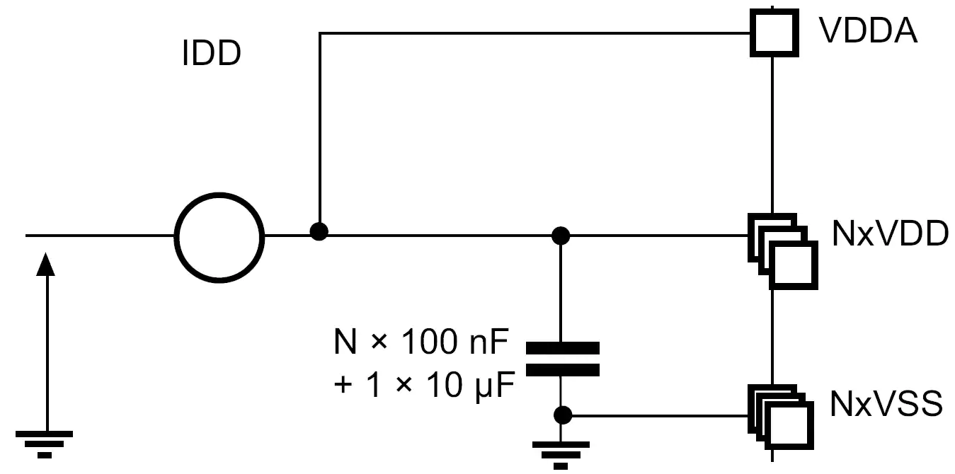
STM32L053のデータシートのセクション6.1.8には、MCUが消費する電流を測定する方法はハイサイドセンシング方式(図2)が好ましいとあります。つまり、電流検出デバイスは電圧供給源と負荷(MCU)の間に配置されます。STM32L053 Discoveryボードは、この方法を用いて電流を測定します。これにより、ユーザー自身の電流測定機器、またはオンボードの電流測定モジュールを使用して、STM32L053C8の消費電流を測定することができます。
DiscoveryボードのジャンパJP4により、IDD測定機能の有効/無効を設定します。図3は、JP4が電流の流れをどのように管理しているかを示す概略図です。ジャンパが1番ピンと 2番ピン(オフ位置)に接続されている場合、VCCはMCUに直接接続され、電流を測定することはできません。ジャンパを2番ピンと3番ピン(オン位置)に接続すると、電流はVCCからIDD測定モジュールを通り、MCUに流れます。この構成では、MCUはモジュールと通信し、瞬時の消費電流をリクエストすることができます。
電流計などの外部機器を使用して電流を測定する場合は、ジャンパを完全に外します。それから、ハイサイド検出方式に従うように、測定器のリード線を1番ピンと2番ピンに接続して回路を完成させます。

IDD測定モジュール
JP4をオンの位置に設定したら、次にユーザーはどのように電流測定値を読み取るのか知る必要があります。Discoveryボードのデータシートには、(測定範囲が100nA~50mAであることを述べている以外には)このトピックに関する情報はありません。ボードの回路図とデモコードから、簡単な操作方法が推測されます。このモジュールは、電流検出抵抗ネットワークとMFX(Multi-Function eXpander)の2つのパーツに分けることができます。抵抗器は、電流の流れに比例した電圧信号を作り出し、それを増幅してからMFXで読み取ります。MFXは、この電圧を電流測定値に変換してMCUに報告するだけでなく、抵抗ネットワークのコントローラとして、MCUが消費する電流量に最適な値に総シャント抵抗を設定します。
電流検出抵抗
図4は、MCUが消費している電流を測定する回路です。この回路には4つの電流検出抵抗(1Ω、24Ω、620Ω、および10kΩ)があり、紫色の枠で強調表示されています。これらの抵抗のうち3つはMOSFETと直列に配置され、そのゲートはMFXのGPIOピンと接続されています。このように、MFXはこれらのMOSFETを様々に組み合わせてオンにすることで、シャント抵抗の総量を変化させることができます。これは、電流の小さな変化を電圧の大きな変化にする一方で、シャント抵抗にかかる増幅された電圧が3.3Vを超えないようにするために必要です。なお、MFXには4番目のMOSFETが接続されており、キャリブレーションに使用されています。
図4には4つのオペアンプがあり、シャント抵抗の電圧降下を増幅するために使用されます。U7BとU7Dの2つのオペアンプは、電流センス抵抗を差動アンプから分離するために、単にボルテージフォロアとして使用されています。U7Cは、利得が49.9になるように選択された抵抗器とともに、このアンプを実現するために使用されます。最後に、U7Aは、差動増幅器に0.14814Vのバイアス電圧を供給するためのボルテージフォロワです。これにより、出力電圧の式は以下のように変化します。
オフセットは、MOSFETの電圧降下を補正するためのものと思われます。

Multi-Function eXpander
MFXは、タッチスクリーンドライバ、I/Oエキスパンダ、およびIDDコントローラとして動作するようにファームウェアをロードしたSTM32L152チップです。STM32L053 Discoveryボードでは、上記の電流測定回路をマスターMCU(STM32L053C8)から切り離すために、これらの機能のうち最後のものだけが利用されます。I2Cバスを使用して、MCUはmfxstm32l152.hファイルで定義されたレジスタを設定することにより、MFX(アドレス 0x84)を制御することができます。このファイルはSTM32CubeL0パッケージに含まれ、en.stm32cubel0/STM32Cube_FW_L0_V1.6.0/Drivers/BSP/Components/mfxstm32l152に移動することで参照可能です。本セクションの最後に掲載した Excelドキュメント「MFXSTM32L152_registers.xlsx」は、MFX共通レジスタおよびIDD制御レジスタのレジスタマップです。
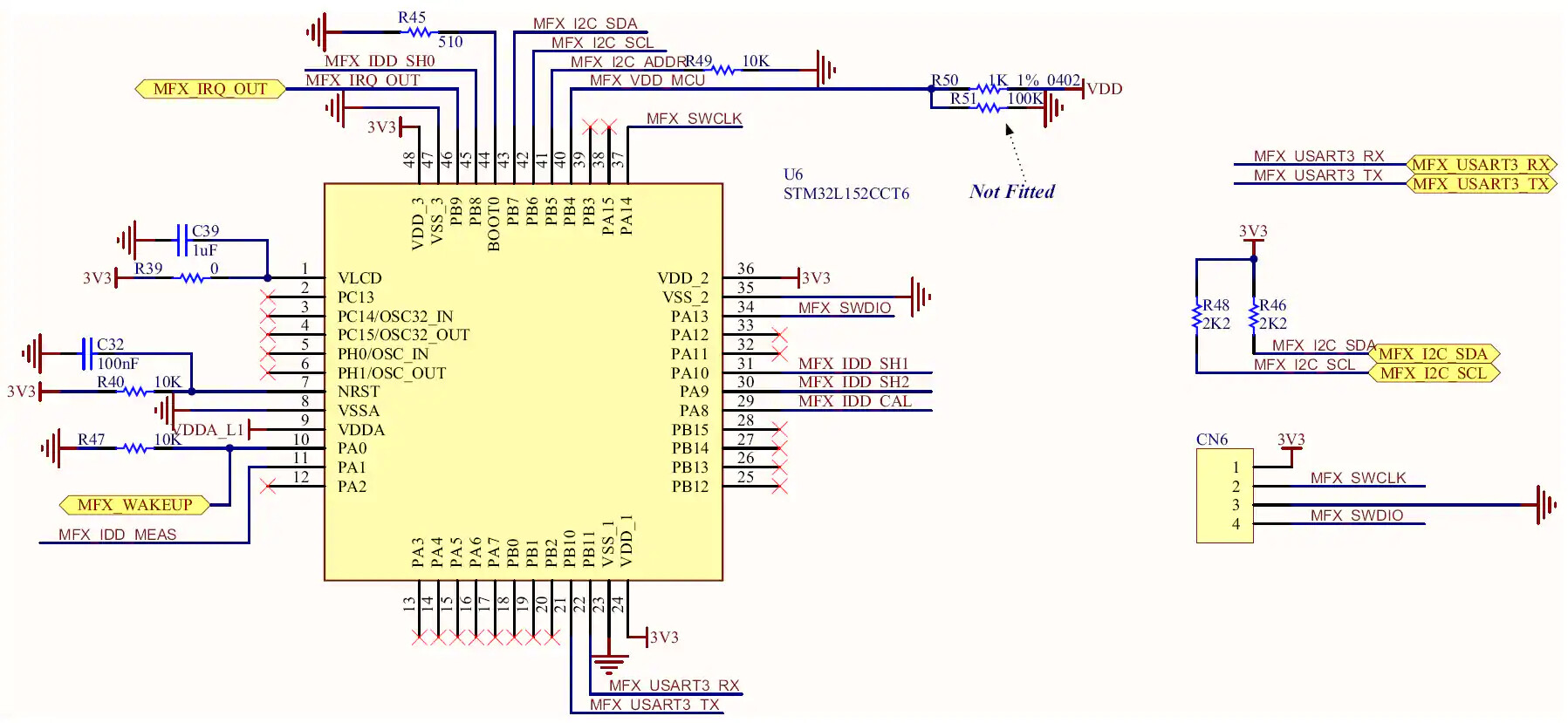
図5はMFXの回路図です。図5と図4で共通するネットのラベルに注目すると、MFXが抵抗ネットワークとどのようにインターフェースしているかがわかります。しかし、より重要なのは、黄色い塗りつぶしの六角形で囲まれたラベルです。これらは、Discoveryボード上の他のチップとのインターフェースに使用される双方向ポートです。特に、MFX_I2C_SDA、MFX_I2C_SCL、MFX_IRQ_OUT、およびMFX_WAKEUPポートは、MFXとMCU間の通信を実現するポートです。これらのポートは、STM32L053C8のピンPB9、PB8、PC13、およびPA1にそれぞれ接続されています。
MFXの公式ドキュメントがないため、STM32L053 Discoveryボードのデモアプリケーションを調査して、正しい初期化手順を決定する必要がありました。このデモアプリケーションもSTM32CubeL0フォルダにあり、電流測定に使用する特定のファイルは
en.stm32cubel0/STM32Cube_FW_L0_V1.6.0/Projects/STM32L053C8-Discovery/Demonstrations/Modules/iddmeasurementディレクトリにありました。これらのファイルから、シャント抵抗を適切に制御し、MCUに割り込み信号を送信するのに、MFXをどのように初期化すべきかを示すために、リスト1のサンプル関数を作成しました。基本的な手順は、以下のとおりです。
-
MFXを既知の状態にするため、ソフトウェアのリセットを実行します。MFX レジスタのクリア時間を確保するため、この操作の直後に100msの遅延を発生させます。
-
IRQ_OUT信号は、MFXイベントが発生したことをMCUに通知するために設定されます。まず、MFX チップの物理ピンはプッシュプル、アクティブハイ(イベント発生時に MFX_IRQ_OUT ピンの状態がローからハイに変化すること)に設定されます。次に、IRQ_OUT信号をトリガするイベントを選択します。この例では、「IDD」と「ERROR」イベントを選択します。つまり、IDD測定の準備ができたとき、またはMFX内で何らかのエラーが発生したときにIRQ_OUTピンが設定されることになります。
Idd_Init()関数の冒頭で、MCUのPC13ピンが立ち上がりエッジで割り込みをトリガするように設定されていることに注意してください。 -
MFXでIDD測定機能が有効になります。
-
電流測定パラメータをMFXに割り当てます。電流検出抵抗の値や差動アンプのゲインなどが含まれます。また、MFXがリセットされるまでの最低電圧(VDD)も設定します。これらの値を含むレジスタはメモリ内に順次配置されているので(アドレス0x82~0x8F)、このサンプル関数では、書き込む値を配列に詰め、14個の値すべてを一度にメモリブロックに書き込みます。
リスト1: IDD測定用MFXの初期化例
void Idd_Init( void )
{
    uint8_t params[14];

    /* Initialize GPIOs */
    // PC13: recieve MFX_IRQ_OUT signal
    RCC->IOPENR |= RCC_IOPENR_GPIOCEN; // enable clocks
    RCC->APB2ENR |= RCC_APB2ENR_SYSCFGEN; // ENABLE SYSTEM CONFIGURATION CONTROLLER CLOCK
    GPIOC->MODER &= ~( GPIO_MODER_MODE13 ); // Input mode
    // Configure external interrupt on MFX_IRQ_OUT (PC13)
    SYSCFG->EXTICR[3] |= SYSCFG_EXTICR4_EXTI13_PC; // PC13 is source for EXTI
    EXTI->IMR |= EXTI_IMR_IM13; // interrupt request from line 13 masked
    EXTI->RTSR |= EXTI_RTSR_TR13; // rising trigger enabled for input line 13

    // NOTE: I2C pins are configured in I2C_init function
    /* Initialize MFX */
    // reset MFX ( SYS_CTRL = SWRST )
    params[0] = 0x80;
    I2C_Write_Reg( I2C1, 0x84, 0x40, params, 1 );
    delay_ms( 100 );  // Give the registers time to be reset
    // IRQ pin -> push-pull, active high
    // ( IRQ_OUT = OUT_PIN_TYPE_PUSHPULL | OUT_PIN_POLARITY_HIGH )
    params[0] = 0x03;
    I2C_Write_Reg( I2C1, 0x84, 0x41, params, 1 );
    delay_ms( 1 );
    // IRQ source -> error and IDD ( IRQ_SRC_EN = IRQ_ERROR | IRQ_IDD )
    params[0] = 0x06;
    I2C_Write_Reg( I2C1, 0x84, 0x42, params, 1 );
    // Enable IDD function ( SYS_CTRL = IDD_EN )
    params[0] = 0x04;
    I2C_Write_Reg( I2C1, 0x84, 0x40, params, 1 );
    // Assign shunt values, gain value, and min VDD value
    params[0] = 0x03; params[1] = 0xE8;        // SH0 = 1000 mohm
    params[2] = 0x00; params[3] = 0x18;        // SH1 = 24 ohm
    params[4] = 0x02; params[5] = 0x6C;     // SH2 = 620 ohm
    params[6] = 0x00; params[7] = 0x00;        // SH3 = not included
    params[8] = 0x27; params[9] = 0x10;     // SH4 = 10,000 ohm
    params[10] = 0x13; params[11] = 0x7E; // Gain = 49.9 (4990)
    params[12] = 0x0B; params[13] = 0xB8;    // VDD_MIN = 3000 mV
    I2C_Write_Reg( I2C1, 0x84, 0x82, params, 14 );
    /* enable interrupts for external interrupt lines 4 - 15 */
    EXTI->PR |= EXTI_PR_PR13; // clear pending interrupt (if it is pending)
    NVIC_EnableIRQ( EXTI4_15_IRQn );
    NVIC_SetPriority( EXTI4_15_IRQn, IDD_INT_PRIO );
}
MFXが初期化されると、IDDの測定が要求できるようになります。リスト2は、その方法の一例です。最初のステップは、(必要であれば)プリディレイを指定することです。これは、測定が行われるまでの経過時間です。IDD_PRE_DELAYレジスタの最上位ビットを設定すると、プリディレイ値が20ms単位で設定され、クリアすると5ms単位に変更されます。次に、IDD_CTRL レジスタのIDD_CTRL_REQビットとIDD_CTRL_SHUNT_NBビットを設定することにより、測定が要求されます(Excel ドキュメントを参照してください)。Discoveryボードには4つのシャント抵抗があるため、IDD_CTLL_SHUNT_NBフィールドに0x04が書き込まれます。
リスト2: MFXからIDD測定を要求する例
void Idd_req_meas( uint8_t predelay )
{
uint8_t param;
predelay |= 0x80; // IDD_PRE_DELAY |= IDD_PREDELAY_20_MS
I2C_Write_Reg( I2C1, 0x84, 0x81, &predelay, 1 ); //add predelay before Idd measurement
param = 0x09; // IDD_CTRL = ( ( 4 << 1 ) & IDD_CTRL_SHUNT_NB ) | IDD_CTRL_REQ
I2C_Write_Reg( I2C1, 0x84, 0x80, ¶m, 1 ); // request Idd measurement
}
測定の準備ができたら、リスト3に示すように、3つのIDD_VALUEレジスタから読み取ることができます。 ただし、IRQ_ERRORビットが設定されているかどうかを確認するために、最初にIRQ_PENDINGレジスタを読み取る必要があります。IRQ_ERRORビットがセットされている場合、MFXはIDD測定値を読もうとしたときに応答しないことがあります。エラーがなければ、メモリアドレス0x14(IDD_VALUE_MSB)~0x16(IDD_VALUE_LSB)からIDD値を読み出すことができます。その後、IRQ_ACKレジスタのIRQ_IDDビットをセットして、割り込みが受信され処理されたことをMFXに知らせるために、ACK(肯定応答)を送信する必要があります。3バイトのIDD値をすべて合わせると、10nAの単位になることに注意してください。nAに変換するには、単純に10倍してください。
リスト3: MFXからIDDの測定値を読み出す例
int Idd_get_meas( void )
{
    uint8_t temp[3];
    uint8_t ack;

    // check for errors
    I2C_Read_Reg( I2C1, 0x84, 0x08, temp, 1 );
    if ( temp[0] & 0x04 ) // if ( REG_IRQ_PENGDING & IRQ_ERROR )
    {
        Idd_Init();
        CURR_MEAS_POS();  // move cursor to current measurement position
        USART_puts( USART1, "MFX ERROR" );
        return -1;
    }

    I2C_Read_Reg( I2C1, 0x84, 0x14, temp, 3 ); // read current measurement
    ack = 0x02;
    I2C_Write_Reg( I2C1, 0x84, 0x44, &ack, 1 ); // acknowledge Idd from MFX
    return (temp[0]<<16) + (temp[1]<<8) + temp[2];
}
レジスタマップ
前述のとおり、この記事に関連するレジスタをドキュメント化したExcelスプレッドシートが以下に含まれています。mfxstm32l152.hファイルの定義は、アドレスとビットの列を埋めるためにコンパイルされています。また、有用なコメントがあれば、 コメントと許可欄に記入されています。リセット値の欄は、ソフトウェアリセットの直後にすべてのレジスタを読み出すテストを実行して割り出されています。いくつかのレジスタはあまり(あるいはまったく)コメントされておらず、いくつかのビットフィールドは定義されていないため、多くの空白セルが存在します。それでも、このスプレッドシートは、上記の関数例で使用されている一見ランダムに見える16進数が、実際には何を表しているのかを理解したい人にとって、有用なリファレンスになります。
- MFXSTM32L152_registers.zip (13.5 KB)
サンプルアプリケーション
STM32L053 Discoveryキットにプリロードされているデモプログラムでは、タッチセンサで4つの動作モードから選択でき、消費電流が電子ペーパーディスプレイに表示されます。これらは実行モード、スリープモード、低電力スリープモード、およびストップモードです。STのHardware Abstraction Librariesの煩雑さを回避しつつ、STM32L053デバイスの低消費電力機能をさらに強調するために、より少ない周辺回路とボード機能を使用する新しいアプリケーションを作成しました。この新しいサンプルアプリケーションには、デモアプリケーションから除外された2つの低消費電力モード(低消費電力実行モードとスタンバイモード)が含まれており、1秒間に約1回の割合で連続測定が行われます。
端末エミュレータは、このアプリケーションのユーザーインターフェースを提供します。図6は、出力のスクリーンショットです。上部のウィンドウに電流の測定値が表示され、下部のウィンドウに動作モードがリストアップされています。矢印は現在のモードを指し、別のモードを選択するための指示が一番下に表示されています。ボーレートが4800に設定され、ラインフィード(LF)ごとに暗に示されているキャリッジリターン(CR)がある限り、どんな端末エミュレータプログラム(PuTTY、Tera Term、CoolTermなど)でも動作するはずです。STM32L053 Discoveryボードの背面に貼られたシールが「MB1143 B-01」以降である場合、USARTが仮想COMポートとインターフェースできるように、はんだブリッジのSB2とSB3を閉じる必要があります (Discovery ボードのユーザーマニュアルのセクション4.14)。

アプリケーションの中心は有限状態機械(Finite State Machine、FSM)で、各状態は6つの動作モードのうちの1つに対応します。各状態のエントリアクションは、システムクロック、電源制御レジスタ、およびM0+コアレジスタを設定し、デバイスを希望の動作モードにするための関数です。これらの関数はそれぞれenter_<Mode>()という名前であり、<Mode>は以下のRun、LPRun、Sleep、LPSleep、Stop、あるいはStandbyのいずれかに置き換えられます。これらの関数と対応する低消費電力モードについての詳細は、STM32L0シリーズの低消費電力モードのページを参照してください。
FSMとは別に、電流の測定機能を処理するバックグラウンドスレッドがあります。MFXがIRQ_OUTラインをセットして電流測定の準備ができたことを知らせるたびに実行されます(MCUのPC13が外部割り込みのトリガとして使用されることを思い出してください)。このスレッドでは、前のセクションで説明した手順で、電流測定値を取得し、表示し、新たな測定値を要求しています。IDD測定モジュールによって供給される電流測定値の正確さを比較、検証するために、デジタルマルチメータを使用しました。両手法を用いて各モード3回ずつ測定し、その平均値を表1に示しました。マルチメータを使用して安定した測定を行うために、MFXを初期化しないようにしていました。これにより、バックグラウンドスレッドが実行されなくなり、MCUが1秒ごとに一時的に実行モードに入るということがなくなりました。この結果からわかるように、実行モード、スリープモード、および低消費電力スリープモードでは、IDDモジュールの精度が最も良いとは言えませんが、回路の単純さを考慮すれば驚くほどそれに近いことが分かります。
表1: 各動作モードにおけるMCUの消費電流の測定結果の比較
| 実行モード | 3.399 mA | 3.451 mA |
|---|---|---|
| 低消費電力実行モード | 44.052 µA | 44.063 µA |
| スリープモード | 1.331 mA | 1.474 mA |
| 低消費電力スリープモード | 14.179 µA | 15.233 µA |
| ストップモード | 451 nA | 443 nA |
| スタンバイモード | 297 nA | 288 nA |
完全なサンプルコード
このアプリケーションはSTのHardware Abstraction Librariesを利用しない比較的単純なものなので、すべてのコードがmain.cファイル(以下のリスト4で提供)に記述されています。Keil社のµVsion5 IDEを使って書かれたこのアプリケーションは、コメントが多く、非常に論理的に構成されていると思います。Keilの開発ツールに初めて触れる方のために、このアプリケーションをゼロから作成する手順の概要を以下に示します。
- µVision5 を開いて、Project > Manage > Pack Installer…と進みます。
- 左のウィンドウでデバイスを選択します(STMicroelectronics > STM32L0 Series > STM32L053 > STM32L053C8 > STM32L053C8Tx)。
- 右のウィンドウで、「Keil::STM32L0xx_DFP」と「ARM::CMSIS」の隣にあるインストールボタンをクリックします。
- Pack Installerウィンドウを閉じ、Project > New µVision Project…と進みます。
- プロジェクトを格納するフォルダに移動し、プロジェクトの名前(例: STM32L035-DISCO_current_meas)を入力し、Save をクリックします。
- デバイスを選択し(左下のボックスで、STMicroelectronics > STM32L0 Series > STM32L053 > STM32L053C8 > STM32L053C8Tx に移動)、OK をクリックします。
- 「CMSIS」ソフトウェアコンポーネントを展開し、「Core」の横のボックスにチェックを入れます。
- 「Device」ソフトウェアコンポーネントの横にあるドロップダウンメニューから「Standalone」を選択します。「Device」ソフトウェアコンポーネントを展開し、「Startup」の横にあるチェックボックスにチェックを入れます。OKをクリックします。
- プロジェクトメニューの「ターゲット1」を展開し、「ソースグループ1」を右クリックし、「既存のファイルをグループ『ソースグループ1』に追加する…」を選択します。
- main.cが保存されている場所に移動して、main.cを選択し、Addをクリックし、Closeをクリックします。
- Project > Options for Target ‘Target 1’… に進みます。(注意:このオプションを表示させるには、Options for Group ‘Source Group 1’… を開いてから閉じる必要があるかもしれません)
- Debugタブで、右上のドロップダウンメニューからST-Link Debuggerを選択します。
- そのドロップダウンメニューの横にあるSettingsをクリックし、「Flash Download」タブで「Programming Algorithms(STM32L0 64KB Flash)」のオプションのみをクリックし、OKをクリックします。
- もう一度OKをクリックし、Project > Build Target へ進みます。
15.最後に、Flash > Downloadと進んでください(ダウンロードが完了すると、アプリケーションを使用するためにリセットボタンを押さなければならない場合があります)。
すべて順調にいけば、ボードのプログラムは完了です。あとはターミナル・エミュレータを開き、ボーレートを4800に設定し、正しいCOMポートを開くだけで使用できます。なお、端末エミュレータによっては、改行を受信しても自動的にキャリッジリターンを印字しないものがありますので、必要に応じて設定を変更する必要があります。
リスト4: main.c
/*******************************************************************************
*
* Program: Current Meas. (rev2)
*
* Author: Matt Mielke
*
* Company: Digi-Key Electronics
*
* Date: September 21, 2016
*
* Description: This program provides an example of interfacing with the MFX
* in order to provide current measurements for each sleep mode
* offered by the STM32L053C8.
*
* Modifications:
* Date Comment
*---------- ------------------------------------------------------------------
*
*
*******************************************************************************/
/******************************************************************************/
/* Includes */
/******************************************************************************/
#include "stm32l0xx.h"
#include <stdio.h>
/******************************************************************************/
/* Defines */
/******************************************************************************/
// System clocks
#define SYSCLK_FREQ ( SystemCoreClock )
#define AHB_PRESC 1
#define HCLK_FREQ ( SYSCLK_FREQ / AHB_PRESC )
#define APB1_PRESC 1
#define PCLK1_FREQ ( HCLK_FREQ / APB1_PRESC )
#define APB2_PRESC 1
#define PCLK2_FREQ ( HCLK_FREQ / APB2_PRESC )
#define USART1CLK_FREQ PCLK2_FREQ
#define I2C1CLK_FREQ PCLK1_FREQ
// USART
#define U1_BAUD_RATE 4800
#define TERM_USART USART1 // USART periph. that interfaces with terminal
// Finite State Machine (FSM)
#define NUM_STATES 6
#define RUN &fsm[0]
#define LPRUN &fsm[1]
#define SLEEP &fsm[2]
#define LPSLEEP &fsm[3]
#define STOP &fsm[4]
#define STANDBY &fsm[5]
// Interrupts
#define IDD_INT_PRIO 3
#define BTN_INT_PRIO 3
#define USART_INT_PRIO 0
// ANSI Escape Sequences
#define CLEAR_TERMINAL() USART_puts( TERM_USART, "\x1B" "[2J" )
#define CURSOR_HOME() USART_puts( TERM_USART, "\x1B" "[H" )
#define CURSOR_OFF() USART_puts( TERM_USART, "\x1B" "[?25l" )
#define CURSOR_BACK() USART_puts( TERM_USART, "\x1B" "[1D" )
#define SAVE_CURSOR_POS() USART_puts( TERM_USART, "\x1B" "7" )
#define RESTORE_CURSOR_POS() USART_puts( TERM_USART, "\x1B" "8" )
// Application Specific Escape Sequences
#define CURR_MEAS_POS() USART_puts( TERM_USART, "\x1B" "[4;10H" )
#define DEBUG_POS() USART_puts( TERM_USART, "\x1b" "[4;30H" )
#define MESSASAGE_POS() USART_puts( TERM_USART, "\x1B" "[16;3H" )
#define PRINT_UI() USART_puts( TERM_USART, \
" ______________________ \n" \
" | Current Consumption: |\n" \
" |----------------------|\n" \
" | |\n" \
" |______________________|\n" \
" ______________________ \n" \
" | Mode |\n" \
" |----------------------|\n" \
" | 0: Run |\n" \
" | 1: Low-Power Run |\n" \
" | 2: Sleep |\n" \
" | 3: Low-Power Sleep |\n" \
" | 4: Stop |\n" \
" | 5: Standby |\n" \
" |______________________|\n" )
/******************************************************************************/
/* Structures and Enumerations */
/******************************************************************************/
// Each state contains an entry action and an array of pointers to the next
// state corresponding to each possible input.
typedef const struct State
{
void (*entry_action)( void );
const struct State* next[NUM_STATES];
}State_Type;
/******************************************************************************/
/* Function Prototypes */
/******************************************************************************/
void Config_SysClk_HSI16( void );
void Config_SysClk_MSI_131( void );
void delay_ms( int t_ms );
void enter_Run( void );
void enter_LPRun( void );
void enter_Sleep( void );
void enter_LPSleep( void );
void enter_Stop( void );
void enter_Standby( void );
void I2C1_Init( void );
void I2C_Read_Reg( I2C_TypeDef* pI2C, uint16_t dev_addr, uint8_t reg, uint8_t* data, uint8_t count );
void I2C_Write_Reg( I2C_TypeDef* pI2C, uint16_t dev_addr, uint8_t reg, uint8_t* data, uint8_t count );
void Idd_Init( void );
int Idd_get_meas( void );
void Idd_report_meas( int meas );
void Idd_req_meas( uint8_t predelay );
void Idd_RestoreContext(void);
void Idd_SaveContext(void);
void SysTick_Init( double overflow_period );
void USART1_Init( void );
char USART_getc( USART_TypeDef* pUSART );
void USART_putc( USART_TypeDef* pUSART, char character );
void USART_puts( USART_TypeDef* pUSART, char* str );
/******************************************************************************/
/* Global Variables */
/******************************************************************************/
uint8_t user_input = 0; // input to FSM
// the context of the gpio modes are saves in these variables
uint32_t GPIOA_MODER = 0, GPIOB_MODER = 0, GPIOC_MODER = 0;
State_Type fsm[NUM_STATES] = // the FSM
{// entry_action //next state
{ enter_Run, { NULL, LPRUN, SLEEP, LPSLEEP, STOP, STANDBY } },
{ enter_LPRun, { RUN, NULL, RUN, LPSLEEP, RUN, RUN } },
{ enter_Sleep, { RUN, LPRUN, SLEEP, LPSLEEP, STOP, RUN } },
{ enter_LPSleep, { RUN, LPRUN, RUN, LPSLEEP, RUN, RUN } },
{ enter_Stop, { RUN, LPRUN, SLEEP, LPSLEEP, STOP, STANDBY } },
{ enter_Standby, { RUN, LPRUN, SLEEP, LPSLEEP, STOP, STANDBY } },
};
State_Type* curr_state = RUN; // store current state of program
// ANSI escape sequences
const char ModePosition[6][8] = { // position of '>' for each mode
{ "\x1B" "[9;3H" },
{ "\x1B" "[10;3H" },
{ "\x1B" "[11;3H" },
{ "\x1B" "[12;3H" },
{ "\x1B" "[13;3H" },
{ "\x1B" "[14;3H" }, };
/******************************************************************************/
/* Interrupt Service Routines */
/******************************************************************************/
/* Entered if data is recieved from USART1 */
void USART1_IRQHandler( void )
{
if ( USART1->ISR & USART_ISR_RXNE ) // Data was received
{
// NOTE: flag cleared by reading USART1->RDR
user_input = ( USART_getc( USART1 ) & 0xF );
if ( user_input >= NUM_STATES )
{
user_input = NUM_STATES - 1;
}
SCB->SCR &= ~( SCB_SCR_SLEEPONEXIT_Msk ); // go to FSM control loop
}
}
/* Entered if user button is pressed in Stop mode (and only Stop mode) */
void EXTI0_1_IRQHandler( void )
{
if ( EXTI->PR & EXTI_PR_PR0 ) // User button pressed
{
EXTI->PR |= EXTI_PR_PR0; // Acknowledge interrupt
user_input = 0; // enter the RUN state
// disable this external interrupt
EXTI->IMR &= ~( EXTI_IMR_IM0 );
NVIC_DisableIRQ( EXTI0_1_IRQn );
}
}
/* Entered when Idd measurement is ready */
// not recognized by the FSM (it is a background thread)
// (must be entered by software when waking from Standby mode)
void EXTI4_15_IRQHandler( void )
{
if ( EXTI->PR & EXTI_PR_PR13 ) // Idd measurement ready
{
EXTI->PR |= EXTI_PR_PR13; // Acknowledge interrupt
Idd_report_meas( Idd_get_meas() );
Idd_req_meas( 50 ); // 1 second
// ensure USART transmission completes before stopping the peripheral
while ( !( USART1->ISR & USART_ISR_TC ) );
}
}
/*******************************************************************************
* Function: main
* Author: Matt Mielke
* Desctription: This is entry point for the program. As always, SystemInit()
* is called to ensure the system is in a known state. The
* enter_Run funciton will initialize the system frequency and the
* peripherals dependent on that frequency. Then, Idd_Init() will
* initialize the MFX to take current measurements and interrupt
* execution when the measurement is ready.
* Since Standby mode is used in this application (and it
* essentially resets the device) the SBF flag must be checked once
* the system is up and running. If the device was woken up from
* Standby mode, the state of the user button must be checked to
* determine what triggered the wake-up event. If the user button
* is depressed, the user woke the device wanting to re-enter Run
* mode. The the user button is not depressed, the MFX woke the
* device wanting to report a current measurement.
* If the program is executing for the first time, the terminal
* is cleared and the GUI is redrawn. In order to avoid having to
* store the previous state, the terminal can save the last
* position of the '>' character so it can be returned to, cleared,
* and redrawn in the current position. The user interface is
* updated each time the FSM control loop is entered.
* Other than update the user interface, the FSM control loop
* simply uses the user input to change the state of the program.
* These state transistions are defined by the fsm structure above.
* Date: 09-21-16
*******************************************************************************/
int main(void)
{
SystemInit();
enter_Run(); // start program in the running state
/* If we woke up from Standby mode, restore FSM */
if ( PWR->CSR & PWR_CSR_SBF ) // Did we wakeup from standby mode?
{
PWR->CR |= PWR_CR_CSBF; // clear the Standby flag
RCC->IOPENR |= RCC_IOPENR_GPIOAEN; // port A clock enabled
GPIOA->MODER &= ~( GPIO_MODER_MODE0 ); // PA0 in input mode
if ( GPIOA->IDR & GPIO_IDR_ID0 ) // if user button (PA0) is being pressed
{
curr_state = STANDBY;
PWR->CSR &= ~( PWR_CSR_EWUP1 | PWR_CSR_EWUP2 ); // disable wake-up pins
Idd_Init();
Idd_req_meas( 50 ); // request initial measurement (1 second)
}
else // MFX caused wake up, so print current meas. and re-enter Standy mode
{
/* Enable external interrupt 13 */
EXTI->IMR |= EXTI_IMR_IM13; // interrupt request from line 13 masked
EXTI->PR |= EXTI_PR_PR13; // clear pending interrupt (if it is pending)
NVIC_EnableIRQ( EXTI4_15_IRQn );
user_input = 5;
EXTI->SWIER |= EXTI_SWIER_SWI13; // trigger Idd meas. ready interrupt
}
}
/* If this is the first execution, initialize FSM */
else
{
CURSOR_OFF();
CLEAR_TERMINAL();
CURSOR_HOME();
PRINT_UI();
USART_puts( USART1, (char*)ModePosition[user_input] );
USART_putc( USART1, '>' );
SAVE_CURSOR_POS();
MESSASAGE_POS();
USART_puts( USART1, "Press keys 0 - 5 to \n change the power mode " );
Idd_Init();
Idd_req_meas( 50 ); // request initial measurement (1 second)
}
// FSM and GUI control loop
while( 1 )
{
if ( curr_state->next[user_input] != NULL )
{
__disable_irq(); // no interrupts may use the USART right now...
// update position of arrow ('>')
RESTORE_CURSOR_POS();
CURSOR_BACK(); // move cursor back one space
USART_putc( USART1, ' ' ); // overwrite '>'
USART_puts( USART1, (char*)ModePosition[user_input] );
USART_putc( USART1, '>' );
SAVE_CURSOR_POS();
// update state
curr_state = curr_state->next[user_input];
// update instructions for changing state
MESSASAGE_POS(); // move cursor to message position
if ( curr_state == STOP )
{
USART_puts( USART1, "Press the user button \n to enter run mode " );
}
else if ( curr_state == STANDBY )
{
USART_puts( USART1, "Press and hold the user\n button to enter run mode" );
}
else
{
USART_puts( USART1, "Press keys 0 - 5 to \n change the power mode " );
}
// wait for USART transmission to complete
while ( !( USART1->ISR & USART_ISR_TC ) );
__enable_irq(); // ...interrupts may use the USART again
// perform entry action of the new state
curr_state->entry_action();
}
}
return 0; // we should never get here
}
/*******************************************************************************
* Function: Config_SysClk_HSI16
* Author: Matt Mielke
* Desctription: This function will configure the system clock to run at 16 MHz
* using the High Speed Internal 16 MHz oscillator. All other
* oscillators are disabled and the SystemCoreClock global variable
* is update using the SystemCoreClockUpdate() function.
* Date: 09-22-16
*******************************************************************************/
void Config_SysClk_HSI16( void )
{
/* Enable Clock */
RCC->CR |= RCC_CR_HSION; // HSI16 oscillator ON
while ( !( RCC->CR & RCC_CR_HSIRDY ) ); // wait until HSI16 is ready
/* Switch System Clock */
// HSI16 oscillator used as system clock
RCC->CFGR = ( RCC->CFGR & ~RCC_CFGR_SW ) | RCC_CFGR_SW_HSI;
while ( ( RCC->CFGR & RCC_CFGR_SWS ) != RCC_CFGR_SWS_HSI ); // wait until switched
/* Disable other clocks (excluding LSE and LSI) */
RCC->CR &= ~( RCC_CR_MSION | RCC_CR_HSEON | RCC_CR_PLLON );
SystemCoreClockUpdate();
}
/*******************************************************************************
* Function: Config_SysClk_MSI_131
* Author: Matt Mielke
* Desctription: This function will configure the system clock to run at
* 131,072 Hz using the Multi-Speed Internal oscillator. All other
* oscillators are disabled and the SystemCoreClock global variable
* is update using the SystemCoreClockUpdate() function.
* Date: 09-22-16
*******************************************************************************/
void Config_SysClk_MSI_131( void )
{
/* Enable and Configure Clock */
RCC->CR |= RCC_CR_MSION;
RCC->ICSCR = ( RCC->ICSCR & ~RCC_ICSCR_MSIRANGE ) | RCC_ICSCR_MSIRANGE_1;
while ( !( RCC->CR & RCC_CR_MSIRDY ) ); // wait until MSI is ready
/* Switch System Clock */
// MSI oscillator used as system clock
RCC->CFGR = ( RCC->CFGR & ~RCC_CFGR_SW ) | RCC_CFGR_SW_MSI;
while ( ( RCC->CFGR & RCC_CFGR_SWS ) != RCC_CFGR_SWS_MSI ); // wait unit switched
/* Disable other clocks (excluding LSE and LSI) */
RCC->CR &= ~( RCC_CR_HSION | RCC_CR_HSEON | RCC_CR_PLLON );
SystemCoreClockUpdate();
}
/*******************************************************************************
* Function: delay_ms
* Author: Matt Mielke
* Desctription: This function assumes the SysTick peripheral is configured to
* underflow every ms. It simply does nothing for t_ms underflows
* in order to delay t_ms milliseconds.
* Date: 09-12-16
*******************************************************************************/
void delay_ms( int t_ms )
{
SysTick->VAL = 0;
while ( t_ms > 0 )
{
while ( !( SysTick->CTRL & SysTick_CTRL_COUNTFLAG_Msk ) ); // wait for underflow
t_ms--;
}
}
/*******************************************************************************
* Function: enter_Run
* Author: Matt Mielke
* Desctription: This function configures the device for run mode. To avoid
* problems entering the low-power modes, the regulator
* configuration is reset right away. Then, the system frequency
* is set to 16MHz and the peripherals dependent on it are
* initialized.
* Date: 09-21-16
*******************************************************************************/
void enter_Run( void )
{
/* Enable Clocks */
RCC->APB1ENR |= RCC_APB1ENR_PWREN;
/* Force the regulator into main mode */
// Reset LPRUN bit
PWR->CR &= ~( PWR_CR_LPRUN );
// LPSDSR can be reset only when LPRUN bit = 0;
PWR->CR &= ~( PWR_CR_LPSDSR );
/* Set HSI16 oscillator as system clock */
Config_SysClk_HSI16();
// Reinitialize peripherals dependent on clock speed
USART1_Init();
SysTick_Init( 0.001 );
I2C1_Init();
}
/*******************************************************************************
* Function: enter_LPRun
* Author: Matt Mielke
* Desctription: This function will configure the system for Low-power run
* mode and enter is using the procedure outlined on page __ of
* reference manual. After enabling/disabling the desired clocks,
* the system frequency is set to 131 kHz. It could be lower than
* this, but serial communication would become more difficult (or
* even impossible). The frequency dependent peripherals are then
* re-initialized and the regulator is forced into low-power mode.
* Date: 09-21-16
*******************************************************************************/
void enter_LPRun( void )
{
/* 1. Each digital IP clock must be enabled or disabled by using the
RCC_APBxENR and RCC_AHBENR registers */
RCC->APB1ENR |= RCC_APB1ENR_PWREN;
/* 2. The frequency of the system clock must be decreased to not exceed the
frequency of f_MSI range1. */
Config_SysClk_MSI_131();
// Reinitialize peripherals dependent on clock speed
USART1_Init();
SysTick_Init( 0.001 );
I2C1_Init();
/* 3. The regulator is forced in low-power mode by software
(LPRUN and LPSDSR bits set ) */
PWR->CR &= ~PWR_CR_LPRUN; // Be sure LPRUN is cleared!
PWR->CR |= PWR_CR_LPSDSR; // must be set before LPRUN
PWR->CR |= PWR_CR_LPRUN; // enter low power run mode
}
/*******************************************************************************
* Function: enter_Sleep
* Author: Matt Mielke
* Desctription: This function will enter Sleep mode by properly configuring
* the SLEEPDEEP bit in the SCR. The SLEEPONEXIT bit is also set as
* the device will only need to be awake to service interrups.
* Also, the Flash is not disabled in order to minimize wake-up
* latency. Sleep mode is entered with the WFI instruction.
* Date: 09-22-16
*******************************************************************************/
void enter_Sleep( void )
{
/* Configure low-power mode */
SCB->SCR &= ~( SCB_SCR_SLEEPDEEP_Msk ); // low-power mode = sleep mode
SCB->SCR |= SCB_SCR_SLEEPONEXIT_Msk; // reenter low-power mode after ISR
/* Ensure Flash memory stays on */
FLASH->ACR &= ~FLASH_ACR_SLEEP_PD;
__WFI(); // enter low-power mode
}
/*******************************************************************************
* Function: enter_LPSleep
* Author: Matt Mielke
* Desctription: This function will put the device in Low-power sleep mode
* by following the procedure described on page __ of the
* reference manual. Power consumption is minimized by disabling
* the Flash and in order to get the regulator into low-power mode,
* the system frequency is decreased to 131 kHz. The necessary
* peripherals are re-initialized and Low-power sleep mode is
* entered through the WFI instuction.
* Date: 09-22-16
*******************************************************************************/
void enter_LPSleep( void )
{
/* 1. The Flash memory can be switched off by using the control bits
(SLEEP_PD in the FLASH_ACR register). This reduces power consumption
but increases the wake-up time. */
FLASH->ACR |= FLASH_ACR_SLEEP_PD;
/* 2. Each digital IP clock must be enabled or disabled by using the
RCC_APBxENR and RCC_AHBENR registers */
RCC->APB1ENR |= RCC_APB1ENR_PWREN;
/* 3. The frequency of the system clock must be decreased to not exceed the
frequency of f_MSI range1. */
// Set MSI 131.072 kHz as system clock
Config_SysClk_MSI_131();
// Reinitialize peripherals dependent on clock speed
USART1_Init();
SysTick_Init( 0.001 );
I2C1_Init();
/* 4. The regulator is forced in low-power mode by software
(LPSDSR bits set ) */
PWR->CR |= PWR_CR_LPSDSR; // voltage regulator in low-power mode during sleep
/* 5. Follow the steps described in Section 6.3.5: Entering low-power mode */
SCB->SCR &= ~( SCB_SCR_SLEEPDEEP_Msk ); // low-power mode = sleep mode
SCB->SCR |= SCB_SCR_SLEEPONEXIT_Msk; // reenter low-power mode after ISR
__WFI(); // enter low-power mode
}
/*******************************************************************************
* Function: enter_Stop
* Author: Matt Mielke
* Desctription: This function will not only configure and enter Stop mode,
* but also configure an external interrupt connected to PA0 (the
* user button) in order to wake the device. In order to use less
* power, V_{REFINT} is disabled, the regulator is placed in
* low-power mode, and the I/O pins are placed in analog mode. Stop
* mode is entered using the WFI instruction and once the device is
* woken, the system is restored to a working state before the
* external interrupt ISR is entered.
* Date: 09-23-16
*******************************************************************************/
void enter_Stop( void )
{
/* Enable Clocks */
RCC->APB1ENR |= RCC_APB1ENR_PWREN;
RCC->IOPENR |= RCC_IOPENR_GPIOAEN;
/* Configure PA0 as External Interrupt */
GPIOA->MODER &= ~( GPIO_MODER_MODE0 ); // PA0 is in Input mode
EXTI->IMR |= EXTI_IMR_IM0; // interrupt request from line 0 not masked
EXTI->RTSR |= EXTI_RTSR_TR0; // rising trigger enabled for input line 0
// Enable interrupt in the NVIC
NVIC_EnableIRQ( EXTI0_1_IRQn );
NVIC_SetPriority( EXTI0_1_IRQn, BTN_INT_PRIO );
/* Prepare to enter stop mode */
PWR->CR |= PWR_CR_CWUF; // clear the WUF flag after 2 clock cycles
PWR->CR &= ~( PWR_CR_PDDS ); // Enter stop mode when the CPU enters deepsleep
// V_REFINT startup time ignored | V_REFINT off in LP mode | regulator in LP mode
PWR->CR |= PWR_CR_FWU | PWR_CR_ULP | PWR_CR_LPSDSR;
RCC->CFGR |= RCC_CFGR_STOPWUCK; // HSI16 oscillator is wake-up from stop clock
SCB->SCR |= SCB_SCR_SLEEPDEEP_Msk; // low-power mode = stop mode
__disable_irq();
Idd_SaveContext();
I2C1->CR1 &= ~I2C_CR1_PE; // Address issue 2.5.1 in Errata
__WFI(); // enter low-power mode
I2C1->CR1 |= I2C_CR1_PE;
Idd_RestoreContext();
__enable_irq(); // <-- go to isr
}
/*******************************************************************************
* Function: enter_Standby
* Author: Matt Mielke
* Desctription: This function will enter Standby mode and enable the devices
* two wake-up pins (PA0 and PC13). This way, either the user
* button or a signal from the MFX can wake the device.
* Date: 09-27-16
*******************************************************************************/
void enter_Standby( void )
{
/* Enable Clocks */
RCC->APB1ENR |= RCC_APB1ENR_PWREN;
/* Prepare for Standby */
// if WKUP pins are already high, the WUF bit will be set
PWR->CSR |= PWR_CSR_EWUP1 | PWR_CSR_EWUP2;
PWR->CR |= PWR_CR_CWUF; // clear the WUF flag after 2 clock cycles
PWR->CR |= PWR_CR_ULP; // V{REFINT} is off in low-power mode
PWR->CR |= PWR_CR_PDDS; // Enter Standby mode when the CPU enters deepsleep
SCB->SCR |= SCB_SCR_SLEEPDEEP_Msk; // low-power mode = stop mode
__WFI(); // enter low-power mode
}
/*******************************************************************************
* Function: I2C1_Init
* Author: Matt Mielke
* Desctription: Pins PB8 and PB9 are configured as the I2C1_SCL and I2C_SDA
* pins, respectively. The timing register of the I2C1 peripheral
* is configured to work across a frequency range of 131072 Hz to
* 32 MHz. This is accomplished by setting the SCLH and SCLL
* bitfields to 5 (as this provides a minumum f_{SCL} of about
* 10 kHz, and setting the SCLDEL and SDADEL bitfields to 0. Note
* that the value of SDADEL is of little concern because
* NOSTRETCH = 0. The value of PRESC is dynamically chosen based
* on the frequency of the I2C1 clock. No interrups are enabled as
* the MFX will alert the device when measurements are ready.
* Date: 09-13-16
*******************************************************************************/
void I2C1_Init( void )
{
int presc; // prescaler
/* Enable Clocks */
RCC->APB1ENR |= RCC_APB1ENR_I2C1EN; // Enable I2C1 clock
RCC->IOPENR |= RCC_IOPENR_GPIOBEN; // Enable GPIOB clock
/* Configure GPIOs */
// PB8 = MFX_I2C_SCL -> alternate function mode
// PB9 = MFX_I2C_SDA -> alternate function mode
GPIOB->MODER &= ~( GPIO_MODER_MODE8 | GPIO_MODER_MODE9 );
GPIOB->MODER |= GPIO_MODER_MODE8_1 | GPIO_MODER_MODE9_1;
// AFSEL8 = 4 -> I2C1_SCL // AFSEL9 = 4 -> I2C1_SDA
GPIOB->AFR[1] |= (4 << 0) | (4 << 4);
GPIOB->OTYPER |= GPIO_OTYPER_OT_8 | GPIO_OTYPER_OT_9; // output open drain
/* Configure I2C1 */
I2C1->CR1 &= ~( I2C_CR1_PE ); // ensure I2C1 is disabled
// Try to configure f_SCL = ~150 kHz
// NOTE: NOSTRETCH must equal 0 (default)
// t_{PRESC} = (PRESC+1) x t_{I2CCLK} -> PRESC = f_{I2CCLK}/f_{PRESC} - 1
presc = I2C1CLK_FREQ / 150000 - 1;
presc = presc < 0 ? 0 : presc; // clip presc to 0 if negative
presc = presc > 15 ? 15 : presc; // clip presc to 15 if larger
I2C1->TIMINGR = 0; // clear TIMINGR
// SCLDEL = 0 // SDADEL = 0 // SCLH = 5 // SCLL = 5 // PRESC = presc
I2C1->TIMINGR |= ( (5<<8) & I2C_TIMINGR_SCLH ) | ( 5 & I2C_TIMINGR_SCLL ) |
( ( presc << 28 ) & I2C_TIMINGR_PRESC );
/* Enable I2C1 */
I2C1->CR1 |= I2C_CR1_PE;
}
/*******************************************************************************
* Function: I2C_Read_Reg
* Author: Matt Mielke
* Desctription: This function will read the contents of the slave's memory
* starting at the specified address. The user must specify which
* I2C peripheral to use, the slave address, the address of the
* register to start from, and the number of bytes to be read.
* Also, a buffer for the data to be stored in must be provided.
* Date: 09-13-16
*******************************************************************************/
void I2C_Read_Reg( I2C_TypeDef* pI2C, uint16_t dev_addr, uint8_t reg, uint8_t* data, uint8_t count )
{
uint32_t temp_CR2;
// begin transaction by sending the register address
temp_CR2 = pI2C->CR2;
temp_CR2 &= ~( I2C_CR2_RELOAD | I2C_CR2_NBYTES | I2C_CR2_RD_WRN | I2C_CR2_SADD | I2C_CR2_AUTOEND );
temp_CR2 |= ( dev_addr & I2C_CR2_SADD ) | ( ( 1 << 16 ) & I2C_CR2_NBYTES )
| I2C_CR2_START;
pI2C->CR2 = temp_CR2;
while ( !( pI2C->ISR & I2C_ISR_TXIS ) ); // wait for TXDR to be empty
pI2C->TXDR = reg; // send register address
while ( !( pI2C->ISR & I2C_ISR_TC ) ); // wait for transfer to complete
// continue transaction by reading from slave
temp_CR2 = pI2C->CR2;
temp_CR2 &= ~( I2C_CR2_RELOAD | I2C_CR2_NBYTES | I2C_CR2_SADD );
temp_CR2 |= ( dev_addr & I2C_CR2_SADD ) | ( ( count << 16 ) & I2C_CR2_NBYTES )
| I2C_CR2_RD_WRN | I2C_CR2_AUTOEND | I2C_CR2_START;
pI2C->CR2 = temp_CR2;
do
{
while ( !( pI2C->ISR & I2C_ISR_RXNE ) ); // wait for data to be received
*data = pI2C->RXDR;
data++;
count--;
} while ( count > 0 );
while ( !( pI2C->ISR & I2C_ISR_STOPF ) ); // wait for stop to be detected
pI2C->ICR |= I2C_ICR_STOPCF; // clear the stop detection flag
}
/*******************************************************************************
* Function: I2C_Write_Reg
* Author: Matt Mielke
* Desctription: This function will write to the slave's memory starting at the
* provided starting address. Besides this, the I2C peripheral to
* be used, the slave address, the number of bytes to write,
* and a buffer containing the data to be written must be provided.
* Date: 09-13-16
*******************************************************************************/
void I2C_Write_Reg( I2C_TypeDef* pI2C, uint16_t dev_addr, uint8_t reg, uint8_t* data, uint8_t count )
{
uint32_t temp_CR2;
// begin transaction
temp_CR2 = pI2C->CR2;
temp_CR2 &= ~( I2C_CR2_RELOAD | I2C_CR2_NBYTES | I2C_CR2_RD_WRN | I2C_CR2_SADD );
temp_CR2 |= ( dev_addr & I2C_CR2_SADD ) | ( ( ( count + 1 ) << 16 ) & I2C_CR2_NBYTES )
| I2C_CR2_AUTOEND | I2C_CR2_START;
pI2C->CR2 = temp_CR2;
while ( !( pI2C->ISR & I2C_ISR_TXIS ) ); // wait for TXDR to be empty
pI2C->TXDR = reg; // send register address
// send data
do
{
while ( !( pI2C->ISR & I2C_ISR_TXIS ) ); // wait for TXDR to be empty
pI2C->TXDR = *data;
data++;
count--;
} while ( count > 0 );
while ( !( pI2C->ISR & I2C_ISR_TXE) ); // TXDR is empty and all data has been sent
while ( !( pI2C->ISR & I2C_ISR_STOPF ) ); // wait for stop to be detected
pI2C->ICR |= I2C_ICR_STOPCF; // clear the stop detection flag
}
/*******************************************************************************
* Function: Idd_Init
* Author: Matt Mielke
* Desctription: This function will initialize the MFX based to the hardware
* included on the Discovery board. This includes the number of
* shunts, amplifier gain, and MFX interrupt pin configuration.
* The majority of the initialization was taken from the power.c
* file used in the demo application for this Discovery board. Four
* functions are defined in this file to measuere the current in
* different low power modes, and each of them initializes the MFX
* in the same way.
* NOTE: this function assumes that the I2C lines have already been
* initialized.
* Date: 09-14-16
*******************************************************************************/
void Idd_Init( void )
{
uint8_t params[14];
/* Initialize GPIOs */
// PC13: recieve MFX_IRQ_OUT signal
RCC->IOPENR |= RCC_IOPENR_GPIOCEN; // enable clocks
RCC->APB2ENR |= RCC_APB2ENR_SYSCFGEN; // ENABLE SYSTEM CONFIGURATION CONTROLLER CLOCK
GPIOC->MODER &= ~( GPIO_MODER_MODE13 ); // Input mode
// Configure external interrupt on MFX_IRQ_OUT (PC13)
SYSCFG->EXTICR[3] |= SYSCFG_EXTICR4_EXTI13_PC; // PC13 is source for EXTI
EXTI->IMR |= EXTI_IMR_IM13; // interrupt request from line 13 masked
EXTI->RTSR |= EXTI_RTSR_TR13; // rising trigger enabled for input line 13
// NOTE: I2C pins are configured in I2C_init function
/* Initialize MFX */
// reset MFX ( SYS_CTRL = SWRST )
params[0] = 0x80;
I2C_Write_Reg( I2C1, 0x84, 0x40, params, 1 );
delay_ms( 100 ); // Give the registers time to be reset
// IRQ pin -> push-pull, active high
// ( IRQ_OUT = OUT_PIN_TYPE_PUSHPULL | OUT_PIN_POLARITY_HIGH )
params[0] = 0x03;
I2C_Write_Reg( I2C1, 0x84, 0x41, params, 1 );
delay_ms( 1 );
// IRQ source -> error and IDD ( IRQ_SRC_EN = IRQ_ERROR | IRQ_IDD )
params[0] = 0x06;
I2C_Write_Reg( I2C1, 0x84, 0x42, params, 1 );
// Enable IDD function ( SYS_CTRL = IDD_EN )
params[0] = 0x04;
I2C_Write_Reg( I2C1, 0x84, 0x40, params, 1 );
// Assign shunt values, gain value, and min VDD value
params[0] = 0x03; params[1] = 0xE8; // SH0 = 1000 mohm
params[2] = 0x00; params[3] = 0x18; // SH1 = 24 ohm
params[4] = 0x02; params[5] = 0x6C; // SH2 = 620 ohm
params[6] = 0x00; params[7] = 0x00; // SH3 = not included
params[8] = 0x27; params[9] = 0x10; // SH4 = 10,000 ohm
params[10] = 0x13; params[11] = 0x7E; // Gain = 49.9 (4990)
params[12] = 0x0B; params[13] = 0xB8; // VDD_MIN = 3000 mV
I2C_Write_Reg( I2C1, 0x84, 0x82, params, 14 );
/* enable interrupts for external interrupt lines 4 - 15 */
EXTI->PR |= EXTI_PR_PR13; // clear pending interrupt (if it is pending)
NVIC_EnableIRQ( EXTI4_15_IRQn );
NVIC_SetPriority( EXTI4_15_IRQn, IDD_INT_PRIO );
}
/*******************************************************************************
* Function: Idd_get_meas
* Author: Matt Mielke
* Desctription: Once the MFX signals that a current measurement is ready to be
* read, this function can be called to perform the read operation.
* Before the read is performed, the MFX is checked for errors.
* This is because the same interrupt signal that is used to notify
* the host that a measurement is ready is also used to notify the
* host that an error has occured. If we try to read a current
* measurement when an error has occured, the MFX will not respond
* and the code will hang.
* If an error did in fact occur, then the Idd_Init() function is
* called. This will reset the MFX and re-configure it. An error
* message is then printed rather than the current measurement to
* let the user know that an error occured and has been delt with.
* In order to read the current measurement, the IDD_VALUE_MSB,
* IDD_VALUE_MID, and IDD_VALUE_LSB registers must be read. By
* combining the values in these registers, we will have the
* current being consumed in units of 10nA. After these registers
* are read, an acknowledgment is sent to the MFX so it knows that
* we recieved its interrupt signal and responded to it.
* Date: 09-14-16
*******************************************************************************/
int Idd_get_meas( void )
{
uint8_t temp[3];
uint8_t ack;
// check for errors
I2C_Read_Reg( I2C1, 0x84, 0x08, temp, 1 );
if ( temp[0] & 0x04 ) // if ( REG_IRQ_PENGDING & IRQ_ERROR )
{
Idd_Init();
CURR_MEAS_POS(); // move cursor to current measurement position
USART_puts( USART1, "MFX ERROR" );
return -1;
}
I2C_Read_Reg( I2C1, 0x84, 0x14, temp, 3 ); // read current measurement
ack = 0x02;
I2C_Write_Reg( I2C1, 0x84, 0x44, &ack, 1 ); // acknowledge Idd from MFX
return (temp[0]<<16) + (temp[1]<<8) + temp[2];
}
/*******************************************************************************
* Function: Idd_report_meas
* Author: Matt Mielke
* Desctription: This is an application specific function that will convert the
* current measurement value obtained from the MFX to amps and then
* print it at the predefined position on the terminal. If the
* measurement is negative, it is assumed that the measurement is
* not valid and nothing will be printed.
* Date: 09-14-16
*******************************************************************************/
void Idd_report_meas( int meas )
{
char str[12];
if ( meas < 0 )
{
return;
}
sprintf( (char*)str, "%d.%.3dmA", (int)meas/100000, ((int)meas%100000)/100 );
if ( str[0] == '0' )
{
sprintf( (char*)str, "%d.%.3duA", (int)meas/100, ((int)meas%100)*10 );
if ( str[0] == '0' )
{
sprintf( (char*)str, " %dnA ", (int)meas*10 );
}
}
CURR_MEAS_POS(); // move cursor to current measurement position
USART_puts( USART1, str );
USART_puts( USART1, " " );
}
/*******************************************************************************
* Function: Idd_req_meas
* Author: Matt Mielke
* Desctription: This function will request an Idd measurement from the MFX
* with a predelay in units of 20ms. Once the predelay time has
* elapsed, the MFX will sample the current being drawn and use the
* MFX_IRQ_OUT line to signal the host processor that a measurement
* is ready to be read (assuming the IRQ signal was configured and
* enabled in the Idd initialization function).
* Date: 09-14-16
*******************************************************************************/
void Idd_req_meas( uint8_t predelay )
{
uint8_t param;
predelay |= 0x80; // IDD_PRE_DELAY |= IDD_PREDELAY_20_MS
I2C_Write_Reg( I2C1, 0x84, 0x81, &predelay, 1 ); //add predelay before Idd measurement
param = 0x09; // IDD_CTRL = ( ( 4 << 1 ) & IDD_CTRL_SHUNT_NB ) | IDD_CTRL_REQ
I2C_Write_Reg( I2C1, 0x84, 0x80, ¶m, 1 ); // request Idd measurement
}
/*******************************************************************************
* Function: Idd_RestoreContext
* Author: Matt Mielke
* Desctription: This function uses the following global variables:
* GPIOA_MODER, GPIOB_MODER, and GPIOC_MODER. Assuming the function
* Idd_SaveContext was called before this one, the GPIOx_MODER
* registers will be restored to their original values, taking the
* GPIO pins out of analog mode. Interrupts should not be enabled
* while this function is executing, which is why code is added at
* the beginning and end to disable and reenable interrupts if they
* weren't already disabled when this function was called.
* Date: 09-23-16
*******************************************************************************/
void Idd_RestoreContext(void)
{
char was_waiting = 0;
// disable interrupts if they weren't already disabled
if ( __get_PRIMASK() )
{
was_waiting = 1;
}
else
{
__disable_irq();
}
// Enable GPIO clocks
RCC->IOPENR |= RCC_IOPENR_GPIOAEN | RCC_IOPENR_GPIOBEN | RCC_IOPENR_GPIOCEN;
GPIOA->MODER = GPIOA_MODER; // dummy write
// Restore the previous mode of the I/O pins
GPIOA->MODER = GPIOA_MODER;
GPIOB->MODER = GPIOB_MODER;
GPIOC->MODER = GPIOC_MODER;
// enable interrupts if they were enabled before this function was called
if ( !was_waiting )
{
__enable_irq();
}
}
/*******************************************************************************
* Function: Idd_SaveContext
* Author: Matt Mielke
* Desctription: In this function, the state of the GPIOx_MODER registers are
* save into global variables GPIOA_MODER, GPIOB_MODER, and
* GPIOC_MODER. The MODER registers are all then configured to
* analog mode. This will prevent the GPIO pins from
* consuming any current, not including the external interrupts.
* Interrupts should not be enabled while this function is
* executing which is why code is added at the beginning and end
* to disable and reenable interrupts if they weren't already
* disabled when this function was called.
* Date: 09-23-16
*******************************************************************************/
void Idd_SaveContext(void)
{
char was_waiting = 0;
// disable interrupts if they weren't already disabled
if ( __get_PRIMASK() )
{
was_waiting = 1;
}
else
{
__disable_irq();
}
// Enable GPIO clocks
RCC->IOPENR |= RCC_IOPENR_GPIOAEN | RCC_IOPENR_GPIOBEN | RCC_IOPENR_GPIOCEN;
GPIOA_MODER = GPIOA->MODER; // dummy read
// Save the current mode of the I/O pins
GPIOA_MODER = GPIOA->MODER;
GPIOB_MODER = GPIOB->MODER;
GPIOC_MODER = GPIOC->MODER;
// Configure GPIO port pins in Analog Input mode
GPIOA->MODER = 0xFFFFFFFF;
GPIOB->MODER = 0xFFFFFFFF;
GPIOC->MODER = 0xFFFFFFFF;
// Leave the external interrupts alone!
GPIOC->MODER &= ~( GPIO_MODER_MODE13 ); // Input mode
GPIOA->MODER &= ~( GPIO_MODER_MODE0 );
// Disable GPIO clocks
RCC->IOPENR &= ~( RCC_IOPENR_GPIOAEN | RCC_IOPENR_GPIOBEN | RCC_IOPENR_GPIOCEN );
// enable interrupts if they were enabled before this function was called
if ( !was_waiting )
{
__enable_irq();
}
}
/*******************************************************************************
* Function: SysTick_Init
* Author: Matt Mielke
* Desctription: Initializes the SysTick peripheral to underflow every ms.
* Since it will be used in a busy-wait delay function, interrupts
* are dissabled.
* Date: 09-12-16
*******************************************************************************/
void SysTick_Init( double overflow_period )
{
// counter flag set every <overflow_period> seconds
SysTick_Config( (uint32_t)( (double)SYSCLK_FREQ * overflow_period + 0.5 ) );
SysTick->CTRL &= ~( SysTick_CTRL_TICKINT_Msk ); // no systick interrupt
}
/*******************************************************************************
* Function: init_usart1
* Author: Matt Mielke
* Desctription: This function will configure pins PA9 and PA10 as USART1 TX
* RX respectively. The baud rate register is configured
* dynamically based on the system frequency. An interrupt is
* configured to be triggered every time a byte is recived by
* the peripheral.
* NOTE: SB2 and SB3 must be closed on the STM32L0538-DISCO eval
* board.
* Date: 08-30-16
*******************************************************************************/
void USART1_Init( void )
{
/* Enable Clocks */
RCC->APB2ENR |= RCC_APB2ENR_USART1EN; // USART1 clock enabled
RCC->IOPENR |= RCC_IOPENR_GPIOAEN; // Enable GPIOA clock
/* Configre GPIOs */
// PA9 = USART_TX -> alternate function mode
// PA10 = USART_RX -> alternate function mode
GPIOA->MODER &= ~( GPIO_MODER_MODE9 | GPIO_MODER_MODE10 );
GPIOA->MODER |= GPIO_MODER_MODE9_1 | GPIO_MODER_MODE10_1;
GPIOA->AFR[1] = ( 4 << 8 ) | ( 4 << 4 ); // GPIOA, PA9 -> U1TX, PA10 -> U1RX
/* Configure USART1 */
USART1->CR1 &= ~( USART_CR1_UE ); // ensure USART 1 is disabled
USART1->BRR = (uint16_t)( (float)USART1CLK_FREQ / (float)U1_BAUD_RATE + 0.5 ); // set baud rate
USART1->CR1 |= USART_CR1_RE | USART_CR1_TE; // receiver/transmitter enable
/* Enable Interrupts */
USART1->CR1 |= USART_CR1_RXNEIE; // read data register not empty
NVIC_EnableIRQ( USART1_IRQn ); // enable all USART1 interrupts globally
NVIC_SetPriority( USART1_IRQn, USART_INT_PRIO ); // highest priority
/* Enable USART1 */
USART1->CR1 |= USART_CR1_UE;
}
/*******************************************************************************
* Function: USART_getc
* Author: Matt Mielke
* Desctription: This is a blocking function that will spinlock until a byte is
* recieved from the USART.
* Date: 08-30-16
*******************************************************************************/
char USART_getc( USART_TypeDef* pUSART )
{
while ( !( pUSART->ISR & USART_ISR_RXNE ) ); // wait until RX is not empty
return pUSART->RDR;
}
/*******************************************************************************
* Function: USART_putc
* Author: Matt Mielke
* Desctription: Writes a byte to the USART transmit data register once it is
* empty.
* Date: 08-30-16
*******************************************************************************/
void USART_putc( USART_TypeDef* pUSART, char character )
{
while ( !( pUSART->ISR & USART_ISR_TXE ) ); // wait until TDR is empty
pUSART->TDR = character;
}
/*******************************************************************************
* Function: USART_puts
* Author: Matt Mielke
* Desctription: Writes each byte in a string to the USART transmit data
* register.
* Date: 08-30-16
*******************************************************************************/
void USART_puts( USART_TypeDef* pUSART, char* str )
{
while ( *str != '\0' )
{
while ( !( pUSART->ISR & USART_ISR_TXE ) ); // wait until TDR is empty
pUSART->TDR = *str;
str++;
}
}
まとめ
STM32L053 Discoveryボードは、STM32L053ファミリマイクロコントローラの低消費電力機能を評価したい方に最適なツールです。電流測定モジュールを内蔵し、多機能コントローラと連動したシャント抵抗のネットワークにより、電流測定プロセスをMCUから切り離すことができます。このモジュールを使用する上で最も困難なのは、ドキュメントが提供されていないため、初期化処理の方法がわからないことです。そこで、様々なサンプルコードを研究し、IDD測定モジュールと連動させる際のリファレンスとなるよう、充実したコントローラのレジスタマップを作成しました。さらに、モジュールを使用してどのようにSTM32L053C8の各低消費電力モードの消費電流を測定し、報告するかを示す、よりコンパクトなサンプルアプリケーションが、ダイレクトレジスタアクセスを使って記述されています。これにより、追加のライブラリをインポートすることなく、個々の関数をコピーして他のプログラムで使用することができます。