Created by Christopher Jordan - Denny, last modified on Aug 18, 2015
Introduction:
Document Purpose
The purpose of this guide is to get you started with the STM32 and its peripherals. In particular, this guide focuses on the STM32L053R8T6 used on the Nucleo for STM32L0 evaluation board. This guide is targeted for those with a basic understanding of micro-controllers and their operation.
Warning: Code and circuit schematics are provided for reference only
Note: The most updated code will be on GitHub. Please see this for complete code, all code snippets are code references to the GitHub version.
Device Description
ST has provided an affordable and flexible way of developing and prototyping using their STM32 line of micro-controllers. ST’s Nucleo line of evaluation boards is extremely cost effective in comparison with its competitors. You can use one of ST’s 32-bit micro-controllers with DSP capabilities for just about half the price of an Arduino Uno! The Nucleo boards also offer a flexible way of prototyping by using the Arduino form factor along with their own “Morpho Connectors.”This means that you can easily use the shields created for Arduino for prototyping and still have full access to all the micro-controller pins through the Morpho Connector. Also included on the Nucleo boards is an integrated ST-LINK/V2-1 debugger and programmer.
Hardware Used
The hardware that was used in development can be found below. If you would like to order the parts just click on the name to be directed to the Digi-Key part page.
| Device | Part # | Price (USD) | Description | Picture |
|---|---|---|---|---|
| STMicroelectronics NUCLEO-L053R8 | 497-14710-ND | 10.33 | STM32 Micro-controller evaluation board | |
| STMicroelectronics X-NUCLEO-IKS01A1 | 497-15062-ND | 15.25 | ST sensor evaluation board | |
| Adafruit Ultimate GPS Shield | 1528-1045-ND | 49.95 | SD Card, GPS shield for arduino | |
| XBee Pro S1 | XBP24-AWI-001-ND | 32.00 | Wireless Transciever |


Documentation:
Below I have listed the most useful datasheets I used when developing for the micro-controller. I have provided these for the purpose of quick access in hopes to minimize time searching for the correct Datasheet for the information you need.
STM32L053xx Nucleo Board Documents
This is a list of useful datasheets and documents for developing on the STM32L053R8.
| Document Title | Description |
|---|---|
| NUCLEO L053R8 Schematic | Circuit Diagram for the Nucleo STM32L0 Evaluation board |
| STM32L053xx Technical Data | General information, Characteristics and description of capabilities |
| STM32L053xx Reference | Register Descriptions and functionality |
| STM32L053xx Getting Started | Board Schematic, Pin location and descriptions |
| I2C Timing Configuration | Describes Timing Configuration Tool |
STM32L053xx Motion MEMS and environmental Sensor Expansion Board Documents
This is a list of useful datasheets and documents when using some of the sensors produced by ST.
| Document Title | Description |
|---|---|
| X Nucleo ISK01A1 User Manual | Board user manual |
| X Nucleo ISK01A1 Schematic | Board Schematic |
| Temperature Humidity Sensor | Datasheet for temperature and humidity sensor |
| Pressure Sensor | Datasheet for pressure sensor |
| Magnetometer | Datasheet for magnetometer |
| Accelerometer and Gyroscope | Datasheet for accelerometer and Gyro |
Adafruit Ultimate GPS Logger Shield Documents
This is a list of useful datasheets and documents when using the Adafruit Ultimate GPS Shield.
| Document Title | Description |
|---|---|
| Adafruit GPS Shield Schematic | Ultimate GPS Shield Schematic |
| FGPMMOPA6B GPS Module Data sheet | Contains GPS basic data and also NMEA Message format |
| Format and Protocol | Gives more details about NMEA Sentence format |
| PMTK Commands | Contains PMTK commands sent to the GPS module |
XBee Documents
| Document Title | Description |
|---|---|
| XBee Pro Manual | Everything you need to know about the XBee! |
Setup:
Board Setup
Warning: If the maximum current consumption of the NUCLEO and its extension boards exceeds 300mA, it is mandatory to power the NUCLEO using an external power supply connected to E5V or VIN.
Jumpers on the Nucleo board should be checked first for desired operation. This information can also be found in STM32L053xx Getting Started on page 8. Refer to page 16 for the power option setting with JP1 and JP5. The table below describes the Jumper configuration.
| Jumper Name | Jumper Location |
|---|---|
| JP1 | No jumper |
| JP5 | Connecting PWR and U5V |
| JP6 | Add Jumper |
Next you can connect a USB cable, LD1 and LD3 will turn red, meaning you are ready to program. If LD3 does not turn red you must refer to the warning above and read page 16.
Programs
There are many programs to choose from for interacting with the STM32L0 Nucleo Development board, in this case I will be using tools provided by Keil. Once directed to the keil page choose Keil MDK-ARM. The IDE provided by Keil is called µVision and will be the focus of the programming in this guide. At the time of this guide I used keil MDK-ARM version 5.15.
Drivers and Libraries
I would also like to mention the STM32CubeMX software by ST. This software is a GUI interface for C code initializations for the STM32 Series of micro-controllers. It is very helpful for setting up the clock,GPIO,ADC,UART or other peripherals. The reason I will not be using this software is because of the bloated drivers that are generated. It uses HAL(Hardware Abstraction) drivers which provide everything you need to start programming your board. So if you would like to continue using the free lite version of Keil microVision, I would recommend avoiding the HAL libraries.
If you are familiar with STM32 micro-controllers you might be wondering where are the standard peripheral libraries for the L0 series! I have some bad news for you, there aren’t any. The STM32CubeMX which generate the HAL libraries is your only option.
Setting Up Keil MDK-ARM and ST-Link
After signing up with keil and completing your download and installation of Keil a few steps must be completed.
- Within microVision: update the package installation for the STM32L0 Series (Package installer menu path: Project → Manage → Pack installer)
a. ARM::CMSIS Version: 4.3.0 and 4.2.0
b. KEIL::MDK-Middleware Version: 6.4.0 and 6.2.0
c. KEIL:STM32L0xx_DFP Version: 1.3.0
d. KEIL::STM32NUCLEO_BSP Version: 1.3.0
- ST-Link Installation
a. If ST-Link did not install automatically you can always run the .bat file below yourself
b. C:\keil_v5\ARM\STLink\USBDriver and run the .bat file called stlink_winusb_install.bat - Options for Target setup
a. Go to Projects → options for target
b. Choose your device[Device Tab]
c. Ensure your clock is set to 32.0 MHz [Target Tab]
d. Check the box “Use memory layout from target dialog”[Linker Tab]
e. Use ST-Link Debugger and change settings to match picture[Debug Tab]
- That’s all, you should now be ready to program. In addition to the example code on this page, you can also download a couple examples in the package installer within µVision.


Example of Reset and Clock Control (RCC)
Initializing System Core Clock Walk-through
A good reference for all the registers and settings can be found in STM32L053R8 Reference Manual. In this part of the guide we will be setting up the System and Peripheral Clocks. For a visual aid in what we want our final system to look like I have used the STM32CubeMx software to show the settings used. Again this is a visual aid and was not used to generate the code for the clock configuration.

Warning: The USART1CLK and I2C1CLK are not necessarily correct. ONLY the path from HSI RC to blue peripheral clock boxes are correct
As you can see from the above diagram we will use the 16 MHz internal clock and scale it to become 32MHz. To be able to accomplish this we are first going to set the system clock to the internal High Speed Clock (HSI16), then set the flash and power settings then finally setup the PLL to utilize the HSIRC clock and scale it to 32MHz.
STEP1: Enable HSI16
All we have to do here is set HSI16ON bit in the RCC_CR register. Then just wait for the internal high speed clock to be ready by waiting for HSI16RDYF in the RCC_CR register.
Note: For some reason the device header doesn’t call the bits by the name on the datasheet, so the code is correct. Example, you would think HSI16ON would be RCC_CR_HSI16ON but differs to be RCC_CR_HSION.

/* Enable HSI */
  RCC->CR |= ((uint32_t)RCC_CR_HSION);

  /* Wait for HSI to be ready */
while ((RCC->CR & RCC_CR_HSIRDY) == 0){
      // Nop
  }
STEP2: Set HSI to System Clock
Now that we have the HSI enabled we can use it for our system clock by writing to the SW[1:0] bits in the RCC_CFGR register. Then wait for the system clock to be ready.

  /* Set HSI as the System Clock */
RCC->CFGR = RCC_CFGR_SW_HSI;

  /* Wait for HSI to be used for teh system clock */
while ((RCC->CFGR & RCC_CFGR_SWS) != RCC_CFGR_SWS_HSI){
      // Nop
  }
STEP3: Setup FLASH and PWR


FLASH->ACR |= FLASH_ACR_PRFTEN;                          // Enable Prefetch Buffer
FLASH->ACR |= FLASH_ACR_LATENCY;                         // Flash 1 wait state
RCC->APB1ENR |= RCC_APB1ENR_PWREN;                       // Enable the PWR APB1 Clock
PWR->CR = PWR_CR_VOS_0;                                  // Select the Voltage Range 1 (1.8V)
while((PWR->CSR & PWR_CSR_VOSF) != 0);                   // Wait for Voltage Regulator Ready
STEP4: Setup PLL
We now need to configure PLL. The first step is to select the PLLSRC in the RCC_CFGR to be HSI, then set PLLMUL[3:0] to multiply by 4 and lastly set PLLDIV[1:0] to divide by 2.
/* PLLCLK = (HSI * 4)/2 = 32 MHz */
RCC->CFGR &= ~(RCC_CFGR_PLLSRC | RCC_CFGR_PLLMUL | RCC_CFGR_PLLDIV);                /* Clear */
RCC->CFGR |=  (RCC_CFGR_PLLSRC_HSI | RCC_CFGR_PLLMUL4 | RCC_CFGR_PLLDIV2);         /* Set   */
STEP5: Setup Peripheral Clock Divisors
We can leave all the peripherals to have a Divisor of 1.
/* Peripheral Clock divisors */
RCC->CFGR |= RCC_CFGR_HPRE_DIV1;                         // HCLK = SYSCLK
RCC->CFGR |= RCC_CFGR_PPRE1_DIV1;                        // PCLK1 = HCLK
RCC->CFGR |= RCC_CFGR_PPRE2_DIV1;                        // PCLK2 = HCLK
STEP6: Set PLL as System Clock
We need to enable the PLL by writing to PLLON bit in the RCC_CR register. Once we wait for the PLL to be ready by checking the PLLRDY bit in the RCC_CR register we can set it as the system clock by writing to the SW[1:0] bits the appropriate value.
/* Enable PLL */
 RCC->CR &= ~RCC_CR_PLLON;       /* Disable PLL */
 RCC->CR |= RCC_CR_PLLON;        /* Enable PLL     */

   /* Wait until the PLL is ready */
 while((RCC->CR & RCC_CR_PLLRDY) == 0){
       //Nop
   }

   /* Select PLL as system Clock */
 RCC->CFGR &= ~RCC_CFGR_SW;            /* Clear */
 RCC->CFGR |=  RCC_CFGR_SW_PLL;    /* Set   */

   /* Wait for PLL to become system core clock */
 while ((RCC->CFGR & RCC_CFGR_SWS) != RCC_CFGR_SWS_PLL){
       //Nop
   }
Initializing System Core Clock Code:
You can find the full code on GitHub. But you can get the gist of what you should do below.
Timing.c
/**
  \fn          void SystemCoreClockInit(void)
    \brief       SystemCoreClockConfigure: Uses HSI clock
*/
void SystemCoreClockInit(void){
  /* Enable HSI */
    RCC->CR |= ((uint32_t)RCC_CR_HSION);

    /* Wait for HSI to be ready */
  while ((RCC->CR & RCC_CR_HSIRDY) == 0){
        // Nop
    }
    /* Set HSI as the System Clock */
  RCC->CFGR = RCC_CFGR_SW_HSI;

    /* Wait for HSI to be used for teh system clock */
  while ((RCC->CFGR & RCC_CFGR_SWS) != RCC_CFGR_SWS_HSI){
        // Nop
    }

    FLASH->ACR |= FLASH_ACR_PRFTEN;                          // Enable Prefetch Buffer
  FLASH->ACR |= FLASH_ACR_LATENCY;                         // Flash 1 wait state
  RCC->APB1ENR |= RCC_APB1ENR_PWREN;                       // Enable the PWR APB1 Clock
  PWR->CR = PWR_CR_VOS_0;                                  // Select the Voltage Range 1 (1.8V)
  while((PWR->CSR & PWR_CSR_VOSF) != 0);                   // Wait for Voltage Regulator Ready
  /* PLLCLK = (HSI * 4)/2 = 32 MHz */
  RCC->CFGR &= ~(RCC_CFGR_PLLSRC | RCC_CFGR_PLLMUL | RCC_CFGR_PLLDIV);                /* Clear */
  RCC->CFGR |=  (RCC_CFGR_PLLSRC_HSI | RCC_CFGR_PLLMUL4 | RCC_CFGR_PLLDIV2);    /* Set   */

    /* Peripheral Clock divisors */
  RCC->CFGR |= RCC_CFGR_HPRE_DIV1;                         // HCLK = SYSCLK
  RCC->CFGR |= RCC_CFGR_PPRE1_DIV1;                        // PCLK1 = HCLK
  RCC->CFGR |= RCC_CFGR_PPRE2_DIV1;                        // PCLK2 = HCLK
    /* Enable PLL */
  RCC->CR &= ~RCC_CR_PLLON;        /* Disable PLL */
  RCC->CR |= RCC_CR_PLLON;        /* Enable PLL     */

    /* Wait until the PLL is ready */
  while((RCC->CR & RCC_CR_PLLRDY) == 0){
        //Nop
    }

    /* Select PLL as system Clock */
  RCC->CFGR &= ~RCC_CFGR_SW;            /* Clear */
  RCC->CFGR |=  RCC_CFGR_SW_PLL;    /* Set   */

    /* Wait for PLL to become system core clock */
  while ((RCC->CFGR & RCC_CFGR_SWS) != RCC_CFGR_SWS_PLL){
        //Nop
    }
}
Example of GPIO
Initializing GPIO Walk-through
A good reference for all the registers and settings can be found in STM32L053R8 Reference Manual. Lets use the green on-board LED for our example and blue user button by setting up PORTA pin 5 as an output and PORTC pin 13 as input. To verify the location of the LED and blue user button refer to NUCLEO L053R8 Schematic.
STEP1: Setup the Clock
This must be completed first, otherwise the registers will not be affected by changes made! RCC_IOPENR enables different I/O clocks, so we can write to IOPAEN bit and enable PORTA’ s clock.

RCC->IOPENR |= (1UL << 0); // Enable GPIOA clock
STEP2: Setup the mode (input/output etc…)
Since we are using the green LED as an example we want to set PORTA pin 5 as an output pin. In the picture below MODE0…MODE15 labeled in the diagram can be thought of as Pin0…Pin15. We can set pint 5 to output by writing the appropriate bit series to MODE5 bits in the GPIOx_MODER register.

GPIOA->MODER   &= ~((3ul << 2*pin));       // write 00 to pin location
GPIOA->MODER   |=  ((mode << 2*pin));      // Choose mode
STEP3: Setup the output type (Push Pull/Open drain)
If you want you do not have to edit this register as its reset state is Push/Pull, which we want for our LED.
- Open Drain Mode: A “0” in the Output register activates the N-MOS whereas a “1 in the Output register leaves the port in Hi-Z (the P-MOS is never activated).
- Push/Pull: Push-pull mode: A “0” in the Output register activates the N-MOS whereas a “1” in the Output register activates the P-MOS.


GPIOA->OTYPER |= (0 << 5); //Output type Push/Pull
STEP4: Setup Speed
I chose medium speed for the green LED.
- Very Low Speed: 400kHz
- Low Speed: 2MHz
- Medium Speed: 10MHz
- High Speed: 40MHz
GPIOC->OSPEEDR |= ((3 << 2*5)); //medium speed

STEP5: Setup Pull Up/Pull Down register
If you want you do not have to edit this register as its reset state is Push/Pull, which we want for our LED. Please refer to Step 3 Figure 25 for a schematic of the GPIO pin and the pull up and pull down resistors.

GPIOC->PUPDR |= (pupd << 2*5); //No pull up pull down
This Same process can be followed for setting up the blue user button.
Initializing GPIO Code
You can find the full code on GitHub.
GPIO.c
/**
  \fn             void GPIO_Init(GPIO_TypeDef* GPIOx, struct GPIO_Parameters GPIO)
  \brief        Initialize GPIO
    \param        GPIO_TypeDef* GPIOx: Which port to initialize, i.e. GPIOA,GPIOB
    \param        struct GPIO_Parameters GPIO: Structure containing all GPIO parameters:
                        * Pin
                        *    Mode
                        *    Output Type
                        * Output Speed
                        * Pull up / Pull down
*/
void GPIO_Init(GPIO_TypeDef* GPIOx, struct GPIO_Parameters GPIO){

    /* Enable GPIO Clock depending on port */
    if(GPIOx == GPIOA) RCC->IOPENR |= RCC_IOPENR_GPIOAEN;        // Enable GPIOA clock
    if(GPIOx == GPIOB) RCC->IOPENR |= RCC_IOPENR_GPIOBEN;        // Enable GPIOB clock
    if(GPIOx == GPIOC) RCC->IOPENR |= RCC_IOPENR_GPIOCEN;        // Enable GPIOC clock
    if(GPIOx == GPIOD) RCC->IOPENR |= RCC_IOPENR_GPIODEN;        // Enbale GPIOD clock

    /* GPIO Mode Init */
  GPIOx->MODER   &= ~((3ul << 2*GPIO.Pin));               // write 00 to pin location
  GPIOx->MODER   |=  ((GPIO.Mode << 2*GPIO.Pin));        // Choose mode

    /* Output Type Init */
  GPIOx->OTYPER  &= ~((~(GPIO.OType) << GPIO.Pin));

    /* GPIO Speed Init */
  GPIOx->OSPEEDR |=  ((GPIO.Speed << 2*GPIO.Pin));

    /* GPIO PULLUP/PULLDOWN Init */
  GPIOx->PUPDR   |= (GPIO.PuPd << 2*GPIO.Pin);
}

/**
  \fn          void Button_Initialize (void)
  \brief       Initialize User Button
*/
void Button_Initialize(void){

    /* Set port parameters */
    struct GPIO_Parameters GPIO;
    GPIO.Pin    = Blue_Button;
    GPIO.Mode = Input;
    GPIO.OType = Push_Pull;
    GPIO.PuPd = No_PuPd;
    GPIO.Speed = Low_Speed;

    /* Initialize button */
    GPIO_Init(GPIOC,GPIO);
}

/**
  \fn          void LED_Init(void)
  \brief       Initialize LD2
*/
void LED_Init(void){

    /* Set port parameters */
    struct GPIO_Parameters GPIO;
    GPIO.Pin = Green_LED;
    GPIO.Mode = Output;
    GPIO.OType = Push_Pull;
    GPIO.PuPd = No_PuPd;
    GPIO.Speed = High_Speed;

    /* Initialize the LED */
    GPIO_Init(GPIOA,GPIO);
}
GPIO.h
struct GPIO_Parameters
{
    int Pin;
    int Mode;
    int Speed;
    int OType;
    int PuPd;
};
typedef enum Mode_Choices
{
    Input                     = 0,
    Output                    = 1,
    Alternate_Function        = 2,
    Analog_Mode               = 3
}Mode_Choices;
typedef enum OType_Choices
{
    Push_Pull     = 0,
    Open_Drain    = 1
}OType_Choices;
typedef enum Speed_Choices
{
    Very_Low_Speed        = 0,
    Low_Speed             = 1,
    Medium_Speed          = 2,
    High_Speed            = 3
}Speed_Choices;
typedef enum PuPd_Choices
{
    No_PuPd          = 0,
    Pull_Up          = 1,
    Pull_Down        = 2,
}PuPd_Choices;
Setting Alternate Function Walk-through
In many cases you may have to use a GPIO alternate function. In this walk-through I will show how to setup the I2C1_SCL and I2C1_SDA alternate functions on PORTB pin 8 and pin 9 respectively.
STEP1: Find which alternate function is correct
If we look below we can see that we want AF4 to set PB8 and PB9 to I2C1_SCL and I2C1_SDA respectively

STEP2: Write value to the AFRL and AFRH registers

int SCL = 8;                            //SCL pin on PORTB alt fnc 4
int SDA = 9;                            //SDA pin on PORTB alt fnc 4

/*Enable Clock for I2C*/
RCC->APB1ENR |= RCC_APB1ENR_I2C1EN;

/* Enable GPIO Clock */
RCC->IOPENR |=  (1UL << 1);

/** GPIOB Setup
    *    Alternate Mode PORTB pin 8 and pin 9.............(1)
    *    Set alternate function 4 for both pin 8 an 9.....(2)
    */
    GPIOB->MODER = ~((~GPIOB->MODER) | ((1 << 2*SCL) + (1 << 2*SDA)));    /*(1)*/
    GPIOB->AFR[1] = 0x00000044;                                           /*(2)*/
Just a note about writing to AFR registers,
/**
  * Set AFRL to AF_Value on Pin...(1)
  * Set AFRH to AF_Value on Pin...(2)
*/

GPIOB->AFR[0] |= (AF_Value << 4*Pin)       /* (1) */
GPIOB->AFR[1] |= (AF_Value << 4*(Pin - 8)) /* (2) */
Example of ADC
All code can be found on GitHub.
Initializing ADC Walk-through
STEP1: Setup the Clock

RCC->APB2ENR |= (1UL << 9);
STEP2: Enable Built in Calibration

You must make sure that the ADC is not yet enabled, and if it is disable it. You can then set the ADCAL bit which will start the calibration. Then wait for the calibration to finish before clearing it by writing a 1 to EOCAL in the ISR register.
/* Calibration Setup */
if((ADC1->CR & ADC_CR_ADEN) != 0){
    ADC1->CR &= (uint32_t)(~ADC_CR_ADEN);
}

ADC1->CR |= ADC_CR_ADCAL;
while((ADC1->ISR & ADC_ISR_EOCAL) == 0);
ADC1->ISR |= ADC_ISR_EOCAL;
STEP3: Enable ADC

Enable the ADC by writing to the ADEN bit in the CR register. You should then make sure the ADC is ready by checking the ADRDY bit in the ISR register.
/* Enable ADC */
ADC1->CR |= (1UL << 0);

/* Wait for ISR bit to set */
while((ADC1->ISR & 1) == 0);
STEP4: Initialize ADC Pin

ADC1->CHSELR |= (1UL << pin);
STEP5: Configure Resolution, Alignment and mode


/* Enable Continuous mode */
ADC1->CFGR1 |= (1UL << 13);

/* Right Aligned data in DR register */
ADC1->CFGR1 |= (0UL << 5);

/* 12-Bit Resolution */
ADC1->CFGR1 |= (0Ul << 3);
STEP6: Start the conversion and grab the data
/* Start Conversion */
ADC1->CR |= (1UL << 2);

/* Grab the last 12-Bit Data part */
ADC_Conversion = ADC1->DR & 0x00000FFF;
Example of I2C
Initializing I2C Walk-through
A good reference for all the registers and settings can be found in STM32L053R8 Reference Manual. It is also useful to look at the STM32L053xx Tech Data for finding alternate functions for pins. This walk-through assumes you have already setup your alternate function. If you haven’t please refer to Setting Alternate Function Walk-through. In this walk-through we will be setting up I2C1_SCL on PB8 and I2C1_SDA on PB9 respectively.
STEP1: Setup the Clock
You must setup 2 clocks, 1: for enabling the GPIO clock and 2: for enabling the I2C clock
/*Enable Clock for I2C*/
RCC->APB1ENR |= RCC_APB1ENR_I2C1EN;

/* Enable GPIO Clock */
RCC->IOPENR |=  (1UL << 1);
STEP2: Setup I2C Timing Configuration
The easiest way to set this register is to use a tool made by ST called I2C Timing Configuration. It is a tool that runs in Excel and will configure the clock based on your settings.

/** GPIOB Setup
    *    Standard Mode @100kHz with I2CCLK = 16MHz, rise time = 100ns, fall time = 10ns.(1)
    */
    I2C1->TIMINGR = (uint32_t)0x00503D5A;    /*(1)*/
STEP3: Enable I2C
The last step is to enable I2C. This must be the last step in I2C initialization.

I2C1->CR1 |= I2C_CR1_PE; //Enable I2C1 peripheral
Initializing I2C Code
You can find the full code on GitHub.
Note that I have commented out the Interrupt enable for I2C, I decided on a polling method rather than the interrupt for communicating with the various sensors.
I2C.c
/**
  \fn         void I2C_Init(void)
  \brief            I2C initialization
                            *PORTB-8: SCL
                            *PORTB-9: SDA
                            *Digital Noise filter with supression of 1 I2Cclk
                            *fast Mode @400kHz with I2CCLK = 16MHz, rise time = 100ns, fall time = 10ns
*/
void I2C_Init(void){

    int SCL = 8;                            //SCL pin on PORTB alt fnc 4
    int SDA = 9;                            //SDA pin on PORTB alt fnc 4

    /*Enable Clock for I2C*/
    RCC->APB1ENR |= RCC_APB1ENR_I2C1EN;

    /* Enable GPIO Clock */
    RCC->IOPENR |=  (1UL << 1);

    /* Don't forget to also enable which interrupts you want in CR1 */
    //interrupt init
//    NVIC_EnableIRQ(I2C1_IRQn);
//    NVIC_SetPriority(I2C1_IRQn,0);

/** GPIOB Setup
    *    Digital Noise filter with supression of 1 I2Cclk.(1)
    *    Alternate Mode PORTB pin 8 and pin 9.............(2)
    *    Set alternate function 4 for both pin 8 an 9.....(3)
    */
    I2C1->CR1 |= (1<<8);                                                  /*(1)*/
    GPIOB->MODER = ~((~GPIOB->MODER) | ((1 << 2*SCL) + (1 << 2*SDA)));    /*(2)*/
    GPIOB->AFR[1] = 0x00000044;                                           /*(3)*/

/** GPIOB Setup
    *    Standard Mode @100kHz with I2CCLK = 16MHz, rise time = 100ns, fall time = 10ns.(1)
    *    Enable I2C1 peripheral.........................................................(2)
    */
    I2C1->TIMINGR = (uint32_t)0x00503D5A;    /*(1)*/
    I2C1->CR1 |= I2C_CR1_PE;                 /*(2)*/
}
Communicating with HTS221 Temperature/Humidity Sensor Walk-through
A good reference for all the registers and settings can be found in Temperature Humidity Sensor datasheet. In this section of the guide I will describe how to communicate, set up the HTS221 temperature and humidity sensor and read both the temperature and humidity data.
STEP1:Communication Sequence


The following descriptions of the I2C communication is written in the perspective of the master, in my case the STM32L053R8.
The writing sequence can be better described as:
-
Send Start sequence
-
Send Slave Address + read/write (Read = 1,Write=0)
-
Receive Slave Acknowledge (Should be a 0)
-
Send Sub address, which register you want to write to
-
Receive Slave Acknowledge (Should be a 0)
-
Send Data to be written to the register
-
Receive Slave Acknowledge (Should be a 0)
-
Send Stop Sequence
The reading sequence can be better described as:
-
Send Start sequence
-
Send Slave Address + read/write (Read = 1,Write=0)
-
Receive Slave Acknowledge (Should be a 0)
-
Send Subaddress, which register you want to write to
-
Receive Slave Acknowledge (Should be a 0)
-
Send Start sequence again
-
Send Slave Address + read/write (Read = 1,Write=0)
-
Receive Slave Acknowledge (Should be a 0)
-
Receive Data from SUB address
-
Send No Master Acknowledge
-
Send Stop Sequence
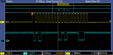
The following communication sequence shows a read on I2C using the STM32L053R8 as the master and the HTS221 as the slave.
Below is an example of what steps 1-3 for reading a register would look like.

This sequence can be broken up:
| Start Condition | Slave Address | Read/Write | Slave Acknowledge |
|---|---|---|---|
| High to low transition | 1011111 | 0 | 0 |
Note: The slave is sending a NACK, so really its saying its Not Not Acknowledged.
Below is an example of steps 4 and 5 .

This sequence can be broken up:
| Sub Address | Slave Acknowledge |
|---|---|
| 00001111 | 0 |
Below is an example of receiving data from the slave steps 6-10 .
This sequence can be broken up:
| Restart Condition | Slave Address | Read/Write | Slave Acknowledge | Sub Address | Nack (Master) |
|---|---|---|---|---|---|
| High to low transition | 1011111 | 1 | 0 | 10111100 | 1 |
Below is an example of the stop sequence step 11 .

STEP2:Communication Sequence Code
You can find the full code on GitHub.
I2C.c
/**
  \fn                    uint32_t I2C_Read_Reg(uint32_t Register)
  \brief            Reads a register, the entire sequence to read (at least for HTS221)
    \param            uint32_t Device: The slave address of the device
    \param            uint32_t Register: The Register to read from
    \returns        uint32_t I2C1_RX_Data: The data read
*/
uint32_t I2C_Read_Reg(uint32_t Device,uint32_t Register){

    //Reset CR2 Register
    I2C1->CR2 = 0x00000000;

    //Check to see if the bus is busy
    while((I2C1->ISR & I2C_ISR_BUSY) == I2C_ISR_BUSY);

    //Set CR2 for 1-byte transfer for Device
    I2C1->CR2 |=(1UL<<16) | (Device<<1);

    //Start communication
    I2C1->CR2 |= I2C_CR2_START;

    //Check Tx empty before writing to it
    if((I2C1->ISR & I2C_ISR_TXE) == (I2C_ISR_TXE)){
        I2C1->TXDR = Register;
    }

    //Wait for transfer to complete
    while((I2C1->ISR & I2C_ISR_TC) == 0);
    //Clear CR2 for new configuration
    I2C1->CR2 = 0x00000000;

    //Set CR2 for 1-byte transfer, in read mode for Device
    I2C1->CR2 |= (1UL<<16) | I2C_CR2_RD_WRN | (Device<<1);

    //Start communication
    I2C1->CR2 |= I2C_CR2_START;

    //Wait for transfer to complete
    while((I2C1->ISR & I2C_ISR_TC) == 0);

    //Send Stop Condition
    I2C1->CR2 |= I2C_CR2_STOP;

    //Check to see if the bus is busy
    while((I2C1->ISR & I2C_ISR_BUSY) == I2C_ISR_BUSY);
    //Clear Stop bit flag
    I2C1->ICR |= I2C_ICR_STOPCF;

    return(I2C1_RX_Data);
}
/**
  \fn                    uint32_t I2C_Read_Reg(uint32_t Register)
  \brief            Reads a register, the entire sequence to read (at least for HTS221)
    \param            uint32_t Device: The slave address to written to
    \param            uint32_t Register: The register that you would like to write to
    \param            uint32_t Data: The data that you would like to write to the register
*/
void I2C_Write_Reg(uint32_t Device,uint32_t Register, uint32_t Data){

    //Reset CR2 Register
    I2C1->CR2 = 0x00000000;

    //Check to see if the bus is busy
    while((I2C1->ISR & I2C_ISR_BUSY) == I2C_ISR_BUSY);

    //Set CR2 for 2-Byte Transfer, for Device
    I2C1->CR2 |= (2UL<<16) | (Device<<1);

    //Start communication
    I2C1->CR2 |= I2C_CR2_START;

    //Check Tx empty before writing to it
    if((I2C1->ISR & I2C_ISR_TXE) == (I2C_ISR_TXE)){
        I2C1->TXDR = Register;
    }

    //Wait for TX Register to clear
    while((I2C1->ISR & I2C_ISR_TXE) == 0);

    //Check Tx empty before writing to it
    if((I2C1->ISR & I2C_ISR_TXE) == I2C_ISR_TXE){
        I2C1->TXDR = Data;
    }

    //Wait for transfer to complete
    while((I2C1->ISR & I2C_ISR_TC) == 0);

    //Send Stop Condition
    I2C1->CR2 |= I2C_CR2_STOP;

    //Check to see if the bus is busy
    while((I2C1->ISR & I2C_ISR_BUSY) == I2C_ISR_BUSY);

    //Clear Stop bit flag
    I2C1->ICR |= I2C_ICR_STOPCF;
}
STEP3: Configure HTS221
For this configuration I have the HTS221 in one-shot mode, which means I just read one set of data at a time. There are two registers that we have to be concerned with for this case.


AV_Conf:
This register is a trade-off of accuracy for power consumption. The more accurate the more power consumed.
- Number of averages for Temperatures set to 16
- Number of averages for Humidity set to 32
CTRL_REG1:
It is important to remember to turn the device on, and then block the data update. The reason for blocking the data update is because the data is 16 bits in length but stored in 8 bit registers. By blocking the data update you must read both the Low and High Data registers before the device will update the value in the register. This prevents you from reading the low bits, the data being updated, and then reading the high bits, leaving you with two different numbers in one of the readings.
- Write 1 to PD
- Write 1 to BDU
Please view the full code on GitHub. Below is the gist of what you should do.
HTS221.c
/**
  \fn                    void HTS221_Init(void)
  \brief            Initialize the HTS221 and check device signature
    \returns        uint8_t Device_Found - Determines if the device was detected
*/
uint8_t HTS221_Init(void){

    //Local variables
    uint8_t Device_Found = 0;
    uint32_t AV_CONF_Init = 0x1B;        /*16 Temp (AVGT) and 32 Hum (AVGT)*/

    //Read data from register and check signature
    I2C_Read_Reg(HTS221_ADDRESS,HTS221_WHO_AM_I);

    //Check if device signature is correct
    if (I2C1->RXDR == HTS221_DEVICE_ID){
        Device_Found = 1;
    }
    else Device_Found = 0;

    /* Setup HTS221_AV_CONF Register */
    if(Device_Found){
        //Set to Default Configuration
        I2C_Write_Reg(HTS221_ADDRESS,HTS221_AV_CONF,AV_CONF_Init);

        //Activate and Block Data Update, this will ensure that both the higher and lower bits are read
        I2C_Write_Reg(HTS221_ADDRESS,HTS221_CTRL_REG1,(HTS221_CTRL_REG1_PD | HTS221_CTRL_REG1_BDU));
    }

    return(Device_Found);
}
STEP4: Read Temperature and Humidity Data
This is definitely the strangest and hardest part, mainly because the datasheet doesn’t really describe what you need to do. But don’t worry I have it all figured out based on the HAL drivers written for the ISK01A1 board. There are two critical equations you need to calculate the temperature and Humidity.
Temperature Interpolation:
Humidity Interpolation:
Look at the calibration registers and output registers to find all the values in the above equations.

Please view the full code on GitHub. Below is the gist of what you should do.
HTS221.c
/**
  \fn                    HTS221_Temp_Read(void)
  \brief            Reads the temperature from HTS221 in one-shot mode
    \returns        float Temperature_In_F: The temperature in Fahrenheit
*/
float HTS221_Temp_Read(void){

    /* Local Variables */
    uint8_t STATUS_REG = 0;

    //T0_degC and T1_degC
    uint16_t T0_degC_x8 = 0;
    uint16_t T1_degC_x8 = 0;
    uint16_t Msb_TO_T1_degC = 0;
    float T0_DegC = 0;
    float T1_DegC = 0;

    //T_OUT
    uint16_t T_OUT_L = 0;
    uint16_t T_OUT_H = 0;
    float T_OUT = 0;

    //T0_OUT and T1_OUT
    int16_t T0_OUT_L = 0;
    int16_t T0_OUT_H = 0;
    int16_t T1_OUT_L = 0;
    int16_t T1_OUT_H = 0;
    float T0_OUT = 0;
    float T1_OUT = 0;

    //Temperature Variables
    float Temperature_In_C = 0;
    float Temperature_In_F = 0;

    //Start a temperature conversion
    I2C_Write_Reg(HTS221_ADDRESS,HTS221_CTRL_REG2,HTS221_CTRL_REG2_ONE_SHOT);

    //Wait for Temperature data to be ready
    do{
        I2C_Read_Reg(HTS221_ADDRESS,HTS221_STATUS_REG);
        STATUS_REG = I2C1->RXDR;
    }while((STATUS_REG & HTS221_STATUS_REG_TDA) == 0);

    //Read Temperature Data and Calibration
    I2C_Read_Reg(HTS221_ADDRESS,HTS221_TEMP_OUT_L);
    T_OUT_L = I2C1->RXDR;

    I2C_Read_Reg(HTS221_ADDRESS,HTS221_TEMP_OUT_H);
    T_OUT_H = I2C1->RXDR;

    I2C_Read_Reg(HTS221_ADDRESS,HTS221_TO_OUT_L);
    T0_OUT_L = I2C1->RXDR;

    I2C_Read_Reg(HTS221_ADDRESS,HTS221_T0_OUT_H);
    T0_OUT_H = I2C1->RXDR;

    I2C_Read_Reg(HTS221_ADDRESS,HTS221_T1_OUT_L);
    T1_OUT_L = I2C1->RXDR;

    I2C_Read_Reg(HTS221_ADDRESS,HTS221_T1_OUT_H);
    T1_OUT_H = I2C1->RXDR;

    I2C_Read_Reg(HTS221_ADDRESS,HTS221_T0_degC_x8);
    T0_degC_x8 = I2C1->RXDR;

    I2C_Read_Reg(HTS221_ADDRESS,HTS221_T1_degC_x8);
    T1_degC_x8 = I2C1->RXDR;

    I2C_Read_Reg(HTS221_ADDRESS,HTS221_T1_T0_Msb);
    Msb_TO_T1_degC = I2C1->RXDR;

    //Process Calibration Registers
    T0_DegC = ((float)(((Msb_TO_T1_degC & 0x3) << 8) | (T0_degC_x8))/8.0);
    T1_DegC = ((float)(((Msb_TO_T1_degC & 0xC) << 6) | (T1_degC_x8))/8.0); //Value in 3rd and 4th bit so only shift 6
    T0_OUT = (float)((T0_OUT_H << 8) | T0_OUT_L);
    T1_OUT = (float)((T1_OUT_H << 8) | T1_OUT_L);
    T_OUT = (float)((T_OUT_H << 8) | T_OUT_L);

    //Calculate Temperatuer using linear interpolation and convert to Fahrenheit
    Temperature_In_C = (float)(T0_DegC + ((T_OUT - T0_OUT)*(T1_DegC - T0_DegC))/(T1_OUT - T0_OUT));
    Temperature_In_F = (Temperature_In_C*(9.0/5.0)) +32.0;

    return(Temperature_In_F);
}
/**
  \fn                    float HTS221_Humidity_Read(void)
  \brief            Reads the Humidity from HTS221 in one-shot mode
    \returns        float Humidity_rH: The relative humidity %
*/
float HTS221_Humidity_Read(void){

    /* Local Variables */
    uint8_t STATUS_REG = 0;

    //H0_rH and H1_rH
    uint8_t H0_rH_x2 = 0;
    float H0_rH = 0;
    uint8_t H1_rH_x2 = 0;
    float H1_rH = 0;
    //H_OUT
    float H_OUT = 0;
    uint16_t H_OUT_L = 0;
    uint16_t H_OUT_H = 0;
    //H0_TO_OUT and H1_TO_OUT
    float H0_T0_OUT = 0;
    float H1_T0_OUT = 0;
    uint16_t H0_T0_OUT_L = 0;
    uint16_t H0_T0_OUT_H = 0;
    uint16_t H1_T0_OUT_L = 0;
    uint16_t H1_T0_OUT_H = 0;
    //Humidity Variables
    float Humidity_rH = 0;

    //Start a humidity conversion
    I2C_Write_Reg(HTS221_ADDRESS,HTS221_CTRL_REG2,HTS221_CTRL_REG2_ONE_SHOT);

    //Wait for Humidity data to be ready
    do{
        I2C_Read_Reg(HTS221_ADDRESS,HTS221_STATUS_REG);
        STATUS_REG = I2C1->RXDR;
    }while((STATUS_REG & HTS221_STATUS_REG_HDA) == 0);

    //Read Humidity data and Calibration
    I2C_Read_Reg(HTS221_ADDRESS,HTS221_H0_rH_x2);
    H0_rH_x2 = I2C1->RXDR;

    I2C_Read_Reg(HTS221_ADDRESS,HTS221_H1_rH_x2);
    H1_rH_x2 = I2C1->RXDR;

    I2C_Read_Reg(HTS221_ADDRESS,HTS221_HUMIDITY_OUT_L);
    H_OUT_L = I2C1->RXDR;

    I2C_Read_Reg(HTS221_ADDRESS,HTS221_HUMIDITY_OUT_H);
    H_OUT_H = I2C1->RXDR;

    I2C_Read_Reg(HTS221_ADDRESS,HTS221_H0_T0_OUT_L);
    H0_T0_OUT_L = I2C1->RXDR;

    I2C_Read_Reg(HTS221_ADDRESS,HTS221_H0_T0_OUT_H);
    H0_T0_OUT_H = I2C1->RXDR;

    I2C_Read_Reg(HTS221_ADDRESS,HTS221_H1_T0_OUT_L);
    H1_T0_OUT_L = I2C1->RXDR;

    I2C_Read_Reg(HTS221_ADDRESS,HTS221_H1_T0_OUT_H);
    H1_T0_OUT_H = I2C1->RXDR;

    //Process Calibration Registers
    H0_rH = (float)H0_rH_x2/2.0;
    H1_rH = (float)H1_rH_x2/2.0;
    H_OUT = (float)((H_OUT_H << 8) | H_OUT_L);
    H0_T0_OUT = (float)((H0_T0_OUT_H << 8) | H0_T0_OUT_L);
    H1_T0_OUT = (float)((H1_T0_OUT_H << 8) | H1_T0_OUT_L);

    //Calculate the relative Humidity using linear interpolation
    Humidity_rH = ( float )(((( H_OUT - H0_T0_OUT ) * ( H1_rH - H0_rH )) / ( H1_T0_OUT - H0_T0_OUT )) + H0_rH );

    return(Humidity_rH);
}
Communicating with LPS25HB Pressure Sensor Walk-through
A good reference for all the registers and settings can be found in Pressure Sensor datasheet. In this section of the guide I will describe how to communicate, set up the LPS25HB pressure sensor and read the pressure sensor data.
STEP1: Communication Sequence
The communication sequence is the same as the HTS221. If you haven’t read this section click here.
STEP2: Configure LPS25HB


Similar to the HTS221 we are going to use one-shot mode and read one data set at a time. We again need to power on the device, and block the data update so we aren’t getting conflicting data (because the data is 24 bits split up into 8 bit registers). All the code can be found on GitHub, but the gist of what you want to do is below.
/**
  \fn                    uint8_t LPS25HB_Init(void))
  \brief            Initializes the LPS25HB Pressure sensor
    \returns         uint8_t Device_Found:  1 - Device found, 0 - Device not found
*/
uint8_t LPS25HB_Init(void){

    uint8_t Device_Found = 0;

    //Read data from register and check signature
    I2C_Read_Reg(LPS25HB_ADDRESS,LPS25HB_WHO_AM_I);

    //Check if device signature is correct
    if (I2C1->RXDR == LPS25HB_DEVICE_ID){
        Device_Found = 1;
    }
    else{
        Device_Found = 0;
    }

    if(Device_Found){
        //Power on the device and Block Data Update
        I2C_Write_Reg(LPS25HB_ADDRESS,LPS25HB_CTRL_REG1,(LPS25HB_CTRL_REG1_PD | LPS25HB_CTRL_REG1_BDU));

        //Configure the resolution for pressure for 16 internal averages
        I2C_Write_Reg(LPS25HB_ADDRESS,LPS25HB_RES_CONF,LPS25HB_RES_CONF_AVGP0);
    }

    return(Device_Found);
}
STEP3: Read Pressure Data
Luckily there is no linear interpolation involved in reading the pressure data. But there is still one operation to complete before getting the pressure reading.

According to the datasheet the pressure sensitivity is 1 bit/hPa, so we must apply the following equation to the 24 bit value.
One other trick we must complete is to convert the two’s compliment 24 bit value into a 32 bit two’s compliment value. This can be done by checking the 24 bit values MSB and then extending the remaining 8 bits with the appropriate value.
//convert the 2's complement 24 bit to 2's complement 32 bit
    if (Raw_Pressure & 0x00800000){
            Raw_Pressure |= 0xFF000000;
    }
All the code can be found on GitHub, but the gist of what should be done can be found below.
LPS25HB.c
/**
  \fn                    void LPS25HB_Configuration(void)
  \brief            Prints important Configuration registers
    \returns        float LPS25HB_Pressure: pressure measured in mbar
*/
float LPS25HB_Pressure_Read(void){

    //Local Variables
    uint8_t PRESS_OUT_XL = 0;
    uint8_t PRESS_OUT_L = 0;
    uint8_t PRESS_OUT_H = 0;
    float Pressure = 0;
    int32_t Raw_Pressure = 0;
    uint8_t LPS25HB_STATUS = 0;

    //Start a temperature conversion
    I2C_Write_Reg(LPS25HB_ADDRESS,LPS25HB_CTRL_REG2,LPS25HB_CTRL_REG2_ONE_SHOT);

    //Wait for Temperature data to be ready
    do{
        I2C_Read_Reg(LPS25HB_ADDRESS,LPS25HB_STATUS_REG);
        LPS25HB_STATUS = I2C1->RXDR;
    }while((LPS25HB_STATUS & LPS25HB_STATUS_REG_PDA) == 0);

    //Read the pressure output registers
    I2C_Read_Reg(LPS25HB_ADDRESS,LPS25HB_PRESS_OUT_XL);
    PRESS_OUT_XL = I2C1->RXDR;

    I2C_Read_Reg(LPS25HB_ADDRESS,LPS25HB_PRESS_OUT_L);
    PRESS_OUT_L = I2C1->RXDR;

    I2C_Read_Reg(LPS25HB_ADDRESS,LPS25HB_PRESS_OUT_H);
    PRESS_OUT_H = I2C1->RXDR;

    //Read the reference Register

    /*    Combine pressure into 24 bit value
            PRESS_OUT_H is the High bits     23 - 16
            PRESS_OUT_L is the mid bits     15 - 8
            PRESS_OUT_XL is the lsb                7 - 0
    */
    Raw_Pressure = ((PRESS_OUT_H << 16) | (PRESS_OUT_L << 8) | (PRESS_OUT_XL));

    //convert the 2's complement 24 bit to 2's complement 32 bit
    if (Raw_Pressure & 0x00800000){
            Raw_Pressure |= 0xFF000000;
    }

    //Calculate Pressure in mbar
    Pressure = (float)Raw_Pressure/4096.0f;

    return(Pressure);
}
Converting Pressure to Altitude
One of the uses for the pressure sensor is to calculate the altitude. I have found a very useful article about the derivation of the correlation between altitude and pressure. You can download this article here, but if you just want the equation for finding the altitude here you go.

As you can see from the above equation, most of the values are constants. There is only one unknown for calculating altitude which is your pressure reading.
/**
  \fn                    ISK01A1_Get_Altitude(void)
  \brief            Calculates the altitude based on the pressure
    \returns        float Z: Altitude calculation in meters
*/
float ISK01A1_Get_Altitude(void){

    /* Calculation should be good up to 11km */
    /* Local Variables */
    const float T0 = 288.15;                            /* Temperatuer at zero altitude, ISA */
    float P = 0.0;                                                /* Measured Pressure                 */
    const float P0 = 101325.0;                        /* Pressure at zero altitude, ISA    */
    const float g = 9.80655;                            /* Acceleration due to gravity       */
    const float L = -0.0065;                            /* Lapse Rate, ISA                   */
    const float R = 287.053;                            /* Gas constant for air              */

    /* Read Pressure */
    P = LPS25HB_Pressure_Read()*100.0;            /* Convert mbar to Pa */

    /* Calculate Altitude in meters */
    ISK01A1.Altitude = (T0/L)*(pow((P/P0),((-L*R)/g))-1);

    return(ISK01A1.Altitude);
}
Communicating with LSM6DS0 Accelerometer/Gyroscope Sensor Walk-through
A good reference for all the registers and settings can be found in Accelerometer and Gyroscope datasheet. In this section of the guide I will describe how to communicate, set up the LSM6DS0 Accelerometer/Gyroscope sensor and read the Roll,Yaw,Pitch,Acceleration in X,Acceleration in Y, and Acceleration in Z.
STEP1: Communication Sequence
The communication sequence is the same as the HTS221. If you haven’t read this section click here.
STEP2: Configure LSM6DS0


This device is slightly different in comparison to the other sensors, because there is no one shot mode, and powering on the device is not similar to the other sensors. This device can be in a couple different states given by the diagram below.

I’ve decided that I want the Accelerometer and Gyro both in an on state, so we must write a value greater than 000(reset) to CTRL_REG1_G for its ODR_G[2:0] bits. By doing this we come out of power down mode and set an Output Data Rate. I decided to select 238Hz as my ODR, which means the device is in normal mode (not low powered) and consumes 4.3 mA of current.
Similar to the other sensors, we still want to write to the BDU bit in the CTRL_REG8 register (because the data is 16 bits split up into 8 bit registers).All the code can be found on GitHub, but the gist of what you want to do is below.
/**
  \fn                    uint8_t LSM6DS0_Init(void)
  \brief            Initialize LSM6DS0 Gyro and accelerometer
    \returns        uint8_t Device_Found: 1 - Device found, 0 - Device not found
*/
uint8_t LSM6DS0_Init(void){

    //Global Variables
    uint8_t Device_Found = 0;

    //Read data from register and check signature
    I2C_Read_Reg(LSM6DS0_ADDRESS,LSM6DS0_WHO_AM_I);

    //Check if device signature is correct
    if (I2C1->RXDR == LSM6DS0_DEVICE_ID){
        Device_Found = 1;
    }
    else Device_Found = 0;

    if(Device_Found){

        //Enable Block Data Update until MSB and LSB read
        I2C_Write_Reg(LSM6DS0_ADDRESS,LSM6DS0_CTRL_REG8,LSM6DS0_CTRL_REG8_BDU);

        //Activate both the gyro and the accelerometer at the same ODR of 238 Hz
        I2C_Write_Reg(LSM6DS0_ADDRESS,LSM6DS0_CTRL_REG1_G,LSM6DS0_CTRL_REG1_G_ODR_G2);
    }

    return(Device_Found);
}
STEP3: Read Sensor Data
This is very similar to the LPS25HB Pressure sensor, all we need to do is convert the raw reading with a simple formula.

By default the device is FS = ±2g for linear acceleration and FS = ±245 dps this means our equations will be.
All the code can be found on GitHub, but the gist of what you want to do is below.
LSM6DS0.c
/**
  \fn                    float LSM6DS0_X_Acceleration_Read(void)
  \brief            Retrieves X-Direction Acceleration
    \returns        float Acceleration_X: Acceleration in mg
*/
float LSM6DS0_X_Acceleration_Read(void){

    //Local Variables
    uint8_t LSM6DS0_STATUS = 0;
    uint8_t Out_X_XL_L = 0;
    uint8_t Out_X_XL_H = 0;
    int16_t Raw_X = 0;
    float Acceleration_X = 0;

    //Wait for acceleration data to be ready
    do{
        I2C_Read_Reg(LSM6DS0_ADDRESS,LSM6DS0_STATUS_REG);
        LSM6DS0_STATUS = I2C1->RXDR;
    }while((LSM6DS0_STATUS & LSM6DS0_STATUS_REG_XLDA) == 0);

    //Read acceleration output registers
    I2C_Read_Reg(LSM6DS0_ADDRESS,LSM6DS0_OUT_X_XL_L);
    Out_X_XL_L = I2C1->RXDR;

    I2C_Read_Reg(LSM6DS0_ADDRESS,LSM6DS0_OUT_X_XL_H);
    Out_X_XL_H = I2C1->RXDR;

    //Combine Lower and upper bits
    Raw_X = ((Out_X_XL_H << 8) | Out_X_XL_L);

    //Calculate acceleration based on FS configuration, see datasheet
    Acceleration_X = (float)Raw_X*0.061f;

    return(Acceleration_X);
}
/**
  \fn                    float LSM6DS0_Y_Acceleration_Read(void)
  \brief            Retrieves Y-Direction Acceleration
    \returns        float Acceleration_Y: Acceleration in mg
*/
float LSM6DS0_Y_Acceleration_Read(void){

    //Local Variables
    uint8_t LSM6DS0_STATUS = 0;
    uint8_t Out_Y_XL_L = 0;
    uint8_t Out_Y_XL_H = 0;
    int16_t Raw_Y = 0;
    float Acceleration_Y = 0;

    //Wait for acceleration data to be ready
    do{
        I2C_Read_Reg(LSM6DS0_ADDRESS,LSM6DS0_STATUS_REG);
        LSM6DS0_STATUS = I2C1->RXDR;
    }while((LSM6DS0_STATUS & LSM6DS0_STATUS_REG_XLDA) == 0);

    //Read acceleration output registers
    I2C_Read_Reg(LSM6DS0_ADDRESS,LSM6DS0_OUT_Y_XL_L);
    Out_Y_XL_L = I2C1->RXDR;

    I2C_Read_Reg(LSM6DS0_ADDRESS,LSM6DS0_OUT_Y_XL_H);
    Out_Y_XL_H = I2C1->RXDR;

    //Combine Lower and upper bits
    Raw_Y = ((Out_Y_XL_H << 8) | Out_Y_XL_L);

    //Calculate acceleration based on FS configuration, see datasheet
    Acceleration_Y = (float)Raw_Y*0.061f;

    return(Acceleration_Y);
}
/**
  \fn                    float LSM6DS0_Z_Acceleration_Read(void)
  \brief            Retrieves Z-Direction Acceleration
    \returns        float Acceleration_Z: Acceleration in mg
*/
float LSM6DS0_Z_Acceleration_Read(void){

    //Local Variables
    uint8_t LSM6DS0_STATUS = 0;
    uint8_t Out_Z_XL_L = 0;
    uint8_t Out_Z_XL_H = 0;
    int16_t Raw_Z = 0;
    float Acceleration_Z = 0;

    //Wait for acceleration data to be ready
    do{
        I2C_Read_Reg(LSM6DS0_ADDRESS,LSM6DS0_STATUS_REG);
        LSM6DS0_STATUS = I2C1->RXDR;
    }while((LSM6DS0_STATUS & LSM6DS0_STATUS_REG_XLDA) == 0);

    //Read acceleration output registers
    I2C_Read_Reg(LSM6DS0_ADDRESS,LSM6DS0_OUT_Z_XL_L);
    Out_Z_XL_L = I2C1->RXDR;

    I2C_Read_Reg(LSM6DS0_ADDRESS,LSM6DS0_OUT_Z_XL_H);
    Out_Z_XL_H = I2C1->RXDR;

    //Combine the lower and upper bits
    Raw_Z = ((Out_Z_XL_H << 8) | Out_Z_XL_L);

    //Calculate acceleration based on FS configuration, see datasheet
    Acceleration_Z = (float)Raw_Z*0.061f;

    return(Acceleration_Z);
}
/**
  \fn                    float LSM6DS0_Gyroscope_Roll_Read(void)
  \brief            Retrieves X-Direction(Roll)
    \returns        float Roll: Roll in mdps
*/
float LSM6DS0_Gyroscope_Roll_Read(void){

    //Local Variables
    uint8_t LSM6DS0_STATUS = 0;
    uint8_t Roll_L = 0;
    uint8_t Roll_H = 0;
    int16_t Raw_Roll = 0;
    float Roll = 0;

    //Wait for roll data to be ready
    do{
        I2C_Read_Reg(LSM6DS0_ADDRESS,LSM6DS0_STATUS_REG);
        LSM6DS0_STATUS = I2C1->RXDR;
    }while((LSM6DS0_STATUS & LSM6DS0_STATUS_REG_GDA) == 0);

    //Read Gyroscope output registers
    I2C_Read_Reg(LSM6DS0_ADDRESS,LSM6DS0_OUT_X_G_L);
    Roll_L = I2C1->RXDR;

    I2C_Read_Reg(LSM6DS0_ADDRESS,LSM6DS0_OUT_X_G_H);
    Roll_H = I2C1->RXDR;

    //Combine lower and upper bits
    Raw_Roll = ((Roll_H << 8) | Roll_L);

    //Calculate Roll based on FS configuration,see datasheet
    Roll = (float)Raw_Roll*8.75f;

    return(Roll);
}
/**
  \fn                    float LSM6DS0_Gyroscope_Pitch_Read(void)
  \brief            Retrieves Y-Direction(Pitch)
    \returns        float Pitch: Pitch in mdps
*/
float LSM6DS0_Gyroscope_Pitch_Read(void){

    //Local Variables
    uint8_t LSM6DS0_STATUS = 0;
    uint8_t Pitch_L = 0;
    uint8_t Pitch_H = 0;
    int16_t Raw_Pitch = 0;
    float Pitch = 0;

    //Wait for pitch data to be ready
    do{
        I2C_Read_Reg(LSM6DS0_ADDRESS,LSM6DS0_STATUS_REG);
        LSM6DS0_STATUS = I2C1->RXDR;
    }while((LSM6DS0_STATUS & LSM6DS0_STATUS_REG_GDA) == 0);

    //Read gyroscope output registers
    I2C_Read_Reg(LSM6DS0_ADDRESS,LSM6DS0_OUT_Y_G_L);
    Pitch_L = I2C1->RXDR;

    I2C_Read_Reg(LSM6DS0_ADDRESS,LSM6DS0_OUT_Y_G_H);
    Pitch_H = I2C1->RXDR;

    //Combine lower and upper bits
    Raw_Pitch = ((Pitch_H << 8) | Pitch_L);

    //Calculate Pitch based on FS configuration,see datasheet
    Pitch = (float)Raw_Pitch*8.75f;

    return(Pitch);
}
/**
  \fn                    float LSM6DS0_Gyroscope_Yaw_Read(void)
  \brief            Retrieves Z-Direction(Yaw)
    \returns        float Yaw: Yaw in mdps
*/
float LSM6DS0_Gyroscope_Yaw_Read(void){

    //Local Variables
    uint8_t LSM6DS0_STATUS = 0;
    uint8_t Yaw_L = 0;
    uint8_t Yaw_H = 0;
    int16_t Raw_Yaw = 0;
    float Yaw = 0;

    //Wait for Yaw data to be ready
    do{
        I2C_Read_Reg(LSM6DS0_ADDRESS,LSM6DS0_STATUS_REG);
        LSM6DS0_STATUS = I2C1->RXDR;
    }while((LSM6DS0_STATUS & LSM6DS0_STATUS_REG_GDA) == 0);

    //Read gyroscope output registers
    I2C_Read_Reg(LSM6DS0_ADDRESS,LSM6DS0_OUT_Z_G_L);
    Yaw_L = I2C1->RXDR;

    I2C_Read_Reg(LSM6DS0_ADDRESS,LSM6DS0_OUT_Z_G_H);
    Yaw_H = I2C1->RXDR;

    //Combine lower and upper bits
    Raw_Yaw = ((Yaw_H << 8) | Yaw_L);

    //Calculate Yaw based on FS configuration,see datasheet
    Yaw = (float)Raw_Yaw*8.75f;

    return(Yaw);
}
Communicating with LIS3MDL Magnetometer Sensor Walk-through
A good reference for all the registers and settings can be found in Magnetometer datasheet. In this section of the guide I will describe how to communicate, set up the LIS3MDL magnetometer sensor and read the magnetic field data in the X,Y and Z directions.
STEP1: Communication Sequence
The communication sequence is the same as the HTS221. If you haven’t read this section click here.
STEP2: Configure the LIS3MDL
There are 4 different registers that you have to concern yourself with.


In CTRL_REG1 we can set the power consumption for the X, Y directions by setting the correct bit sequence for OM[1:0] . The code below sets this to medium performance mode. In addition to this setting we can also set the output data rate by writing the correct bit sequence to DO[2:0]. In the case below I chose to write a 10Hz output data rate.
//Performance Vs. Power consumption XY (medium), and set data rate to 10Hz
I2C_Write_Reg(LIS3MDL_ADDRESS,LIS3MDL_CTRL_REG1,(LIS3MDL_CTRL_REG1_OM0 | LIS3MDL_CTRL_REG1_DO2));

//Full scale = +/- 4 gauss (Default value) - just in case
I2C_Write_Reg(LIS3MDL_ADDRESS,LIS3MDL_CTRL_REG2,0x0);

//Performance Vs. Power consumption Z (medium)
I2C_Write_Reg(LIS3MDL_ADDRESS,LTS3MDL_CTRL_REG4,LIS3MDL_CTRL_REG4_OMZ0);

//Enable BDU so you ensure MSB and LSB have been read
I2C_Write_Reg(LIS3MDL_ADDRESS,LTS3MDL_CTRL_REG5,LIS3MDL_CTRL_REG5_BDU);
STEP3: Read Sensor Data
Similar to the other sensor’s we have to do one small modification to our reading. In my case I have a FS = ±4, which means we need to divide the reading by 6842.

All the code can be found on GitHub, but the gist of what you want to do is below.
LIS3MDL.c
/**
  \fn                    float LIS3MDL_X_Read(void)
  \brief            Reads the magnetic field from the X axis
    \returns         float OUT_X: the magnetic field in mG
*/
float LIS3MDL_X_Read(void){

    //Local variables
    uint8_t LIS3MDL_STATUS = 0;
    uint8_t OUT_X_L = 0;
    uint8_t OUT_X_H = 0;
    float OUT_X = 0;
    int16_t Raw_X = 0;

    //Set device to continuous conversion mode
    I2C_Write_Reg(LIS3MDL_ADDRESS,LTS3MDL_CTRL_REG3,LIS3MDL_CTRL_REG3_MD0);

    //Wait for X coordinate data to be ready
    do{
        I2C_Read_Reg(LIS3MDL_ADDRESS,LIS3MDL_STATUS_REG);
        LIS3MDL_STATUS = I2C1->RXDR;
    }while((LIS3MDL_STATUS & LIS3MDL_STATUS_REG_XDA) == 0);

    //Read X Axis magnetic field
    I2C_Read_Reg(LIS3MDL_ADDRESS,LIS3MDL_OUT_X_L);
    OUT_X_L = I2C1->RXDR;

    I2C_Read_Reg(LIS3MDL_ADDRESS,LIS3MDL_OUT_X_H);
    OUT_X_H = I2C1->RXDR;

    //Process X coordinates
    Raw_X = ((OUT_X_H << 8) | OUT_X_L);

    /*
     *1/6842 = ~0.146 mG/LSB according to datasheet
     */
    OUT_X = (float)Raw_X * 0.146f;        // when using +/- 4 gauss
    return(OUT_X);
}
/**
  \fn                    float LIS3MDL_Y_Read(void)
  \brief            Reads the magnetic field from the Y axis
    \returns         float OUT_Y: the magnetic field in mG
*/
float LIS3MDL_Y_Read(void){

    //Local Variables
    uint8_t LIS3MDL_STATUS = 0;
    uint8_t OUT_Y_L = 0;
    uint8_t OUT_Y_H = 0;
    float OUT_Y = 0;
    int16_t Raw_Y = 0;

    //Set device to continuous conversion mode
    I2C_Write_Reg(LIS3MDL_ADDRESS,LTS3MDL_CTRL_REG3,LIS3MDL_CTRL_REG3_MD0);

    //Wait for X coordinate data to be ready
    do{
        I2C_Read_Reg(LIS3MDL_ADDRESS,LIS3MDL_STATUS_REG);
        LIS3MDL_STATUS = I2C1->RXDR;
    }while((LIS3MDL_STATUS & LIS3MDL_STATUS_REG_YDA) == 0);

    //Read Y Axis magnetic field
    I2C_Read_Reg(LIS3MDL_ADDRESS,LIS3MDL_OUT_Y_L);
    OUT_Y_L = I2C1->RXDR;

    I2C_Read_Reg(LIS3MDL_ADDRESS,LIS3MDL_OUT_Y_H);
    OUT_Y_H = I2C1->RXDR;

    /*
    1/6842 = ~0.146 mG/LSB according to datasheet
    */
    Raw_Y = ((OUT_Y_H << 8) | OUT_Y_L);
    OUT_Y = (float)Raw_Y * 0.146f;        // when using +/- 4 gauss
    return(OUT_Y);
}
/**
  \fn                    float LIS3MDL_Z_Read(void)
  \brief            Reads the magnetic field from the Z axis
    \returns         float OUT_Z: the magnetic field in mG
*/
float LIS3MDL_Z_Read(void){

    //Local Variables
    uint8_t LIS3MDL_STATUS = 0;
    uint8_t OUT_Z_L = 0;
    uint8_t OUT_Z_H = 0;
    float OUT_Z = 0;
    int16_t Raw_Z = 0;

    //Set device to continuous conversion mode
    I2C_Write_Reg(LIS3MDL_ADDRESS,LTS3MDL_CTRL_REG3,LIS3MDL_CTRL_REG3_MD0);

    //Wait for X coordinate data to be ready
    do{
        I2C_Read_Reg(LIS3MDL_ADDRESS,LIS3MDL_STATUS_REG);
        LIS3MDL_STATUS = I2C1->RXDR;
    }while((LIS3MDL_STATUS & LIS3MDL_STATUS_REG_ZDA) == 0);

    //Read Z Axis magnetic field
    I2C_Read_Reg(LIS3MDL_ADDRESS,LIS3MDL_OUT_Z_L);
    OUT_Z_L = I2C1->RXDR;

    I2C_Read_Reg(LIS3MDL_ADDRESS,LIS3MDL_OUT_Z_H);
    OUT_Z_H = I2C1->RXDR;

    Raw_Z = ((OUT_Z_H << 8) | OUT_Z_L);

    /*
    1/6842 = ~0.146 mG/LSB according to datasheet
    */
    OUT_Z = (float)Raw_Z * 0.146f;        // when using +/- 4 gauss
    return(OUT_Z);
}
Example of USART/LPUART
Initializing USART/LPUART Walk-through
A good reference for all the registers and settings can be found in STM32L053R8 Reference Manual. It is also useful to look at the STM32L053xx Tech Data for finding alternate functions for pins. This walk-through assumes you have already setup your alternate function. If you haven’t please refer to Setting Alternate Function Walk-through. In this walk-through we will be setting up a couple UART’s. The STM32L053R8 has a coupe of different UART’s. The first is a normal USART (Universal Synchronous Asynchronous Receiver Transmitter) and the second is a Low Powered UART (LPUART). The LPUART is just about the same as the setup for the USART but I figured I should be thorough.
STEP1: Setup the clock
Its a simple as writing to IOPAEN in the RCC_IOPENR register and also enabling the USART clock by writing to USART1EN in the RCC_APB2ENR register. By default the clock is PCLK.
RCC->IOPENR   |=   RCC_IOPENR_GPIOAEN;      /* Enable GPIOA clock */
RCC->APB2ENR  |=   RCC_APB2ENR_USART1EN;    /* Enable USART#1 clock */
STEP2:Configure the USART BRR

There are a couple of equations to be concerned about when calculating the baud-rate. It is all based on how much you are oversampling or if you are using the LPUART. What is meant by oversampling? All this means is that we will sample a bit stream received by the UART multiple times for each bit. After the sampling has been completed the majority value (either 0 or 1) will be picked as the value.
Warning: When oversampling by 8 you CANNOT just write the calculated USARTDIV value.
When oversampling by 16 bits (default)

You can see that one bit time is sampled 16 times to determine the value.
When oversampling by 8 bits

You can see that one bit time is sampled 8 times to determine the value.
Basically there is a set of rules you must follow to write the correct value to the register. Please refer to STM32L053xx Reference page 759 to verify the steps I have written.
- BRR[2:0] = Calculated USARTDIV[3:0] but shifted once to the right
- BRR[3] = 0, Always!
- BRR[15:4] = USARTDIV[15:4].
When using the LPUART
There is no choice in oversampling, hence this is your only equation for the LPUART.
USART BRR Code:
/* Define statements outside function */
#define PCLK    32000000                                    // Peripheral Clock
#define BAUD    9600                                            // Baud rate

/* Local variables */
uint16_t USARTDIV = 0;
uint16_t USART_FRACTION = 0;
uint16_t USART_MANTISSA = 0;

/* Check to see if oversampling by 8 or 16 to properly set baud rate*/
  if((USART2->CR1 & USART_CR1_OVER8) == 1){
      USARTDIV = PCLK/BAUD;
      USART_FRACTION = ((USARTDIV & 0x0F) >> 1) & (0xB);
      USART_MANTISSA = ((USARTDIV & 0xFFF0) << 4);
      USARTDIV = USART_MANTISSA | USART_FRACTION;
      USART2->BRR = USARTDIV;                                                            /* 9600 Baud with 32MHz peripheral clock 8bit oversampling */
  }
  else{
      USART2->BRR = PCLK/BAUD;                                                        /* 9600 Baud with 32MHz peripheral clock 16bit oversampling */
  }
LPUART BRR Code:
Since our MCU is 32 bit, we only have a max value of 2^32-1 = 4294967295 which cannot handle a value like 256*32,000,000. But we can do a little trick and divide first then multiply, it would look something like this.
/* Define statements outside function */
#define PCLK    32000000                                    // Peripheral Clock
#define BAUD    9600                                            // Baud rate

LPUART1->BRR      = (unsigned long)((256.0f/BAUD)*PCLK);         /* 9600 baud @ 32MHz */
STEP3: Configure the CR1 Register

We want a couple different things from this register. We want to enable RX and TX so we write to both RE and TE . We also want to say what our word length is going to be, we can do this by writing the appropriate value to M[1:0] . Please notice that M0 is in bit position 12 and M1 is in bit position 28.
USART2->CR3    = 0x0000;                                                      /* no flow control */
USART2->CR2    = 0x0000;                                                      /* 1 stop bit */

/* 1 stop bit, 8 data bits */
  USART2->CR1    = ((USART_CR1_RE) |                                          /* enable RX  */
                    (USART_CR1_TE) |                                          /* enable TX  */
                    (USART_CR1_UE) |                                          /* enable USART */
                    (USART_CR1_RXNEIE));                                      /* Enable Interrupt */
Initializing USART/LPUART Code (Reading/Writing Also!)
All the code can be found on GitHub, but the gist of what you want to do is below.
Serial.c
/*------------------------------------------------------------------------------------------------------
 * Name:    Serial.c
 * Purpose: Used to communicat with your computer using USART2
 * Date:         7/14/15
 * Author:    Christopher Jordan - Denny
 *------------------------------------------------------------------------------------------------------
 * Note(s):    SER_PutChar are used to redefine printf function
 *----------------------------------------------------------------------------------------------------*/
/*-------------------------------------------------Include Statements---------------------------------*/
#include "stm32l0xx.h"                  // Specific Device header
#include "Serial.h"
/*-------------------------------------------------Define Statements----------------------------------*/
#define PCLK    32000000                                    // Peripheral Clock
#define BAUD    9600                                            // Baud rate
/*-------------------------------------------------Functions------------------------------------------*/
/**
  \fn          void SER_Initialize (void)
  \brief       Initializes USART2 to be used with the serial monitor
*/

void SER_Initialize (void){
  /* Local variables */
  uint16_t USARTDIV = 0;
  uint16_t USART_FRACTION = 0;
  uint16_t USART_MANTISSA = 0;
  RCC->IOPENR   |=   ( 1ul <<  0);         /* Enable GPIOA clock   */
  RCC->APB1ENR  |=   ( 1ul << 17);         /* Enable USART#2 clock */
  /* Configure PA3 to USART2_RX, PA2 to USART2_TX */
  GPIOA->AFR[0] &= ~((15ul << 4* 3) | (15ul << 4* 2) );
  GPIOA->AFR[0] |=  (( 4ul << 4* 3) | ( 4ul << 4* 2) );
  GPIOA->MODER  &= ~(( 3ul << 2* 3) | ( 3ul << 2* 2) );
  GPIOA->MODER  |=  (( 2ul << 2* 3) | ( 2ul << 2* 2) );
  /* Check to see if oversampling by 8 or 16 to properly set baud rate*/
  if((USART2->CR1 & USART_CR1_OVER8) == 1){
      USARTDIV = PCLK/BAUD;
      USART_FRACTION = ((USARTDIV & 0x0F) >> 1) & (0xB);
      USART_MANTISSA = ((USARTDIV & 0xFFF0) << 4);
      USARTDIV = USART_MANTISSA | USART_FRACTION;
      USART2->BRR = USARTDIV;                                                            /* 9600 Baud with 32MHz peripheral clock 8bit oversampling */
  }
  else{
      USART2->BRR = PCLK/BAUD;                                                        /* 9600 Baud with 32MHz peripheral clock 16bit oversampling */
  }
  USART2->CR3   = 0x0000;                 /* no flow control */
  USART2->CR2   = 0x0000;                 /* 1 stop bit */

    /* 1 stop bit, 8 data bits */
  USART2->CR1    = ((USART_CR1_RE) |                                                /* enable RX  */
                     (USART_CR1_TE) |                                                /* enable TX  */
                     (USART_CR1_UE) |                                          /* enable USART */
                                         (USART_CR1_RXNEIE));                                        /* Enable Interrupt */
}
/**
  \fn                    char SER_PutChar(char ch)
  \brief            Put character to the serial monitor
    \param            char ch: Character to send to the serial monitor
    \returns        char ch: The character that was sent to the serial monitor
*/
char SER_PutChar(char ch){
    //Wait for buffer to be empty
  while ((USART2->ISR & USART_ISR_TXE) == 0){
            //Nop
    }

    //Send character
  USART2->TDR = (ch);
  return (ch);
}
/**
  \fn                    int SER_GetChar(void)
  \brief            Get character from the serial monitor
    \returns        int USART2->RDR: The value of character from the serial monitor
*/
int SER_GetChar(void){
  if (USART2->ISR & USART_ISR_RXNE)
    return (USART2->RDR);
  return (-1);
}
Redirecting Printf
There is a great trick that you can do to use the printf function in C with one of your USART’s. As always All the code can be found on GitHub.
/*------------------------------------------------------------------------------------------------------
 * Name:    Retarget.c
 * Purpose: Retargets printf C function to be used with USART2
 * Date:         7/14/15
 * Author:    Christopher Jordan - Denny
 *------------------------------------------------------------------------------------------------------
 * Note(s):    This is really just magic
 *----------------------------------------------------------------------------------------------------*/
/*--------------------------------------Include Statements--------------------------------------------*/
#include <stdio.h>
#include <rt_misc.h>
#include "Serial.h"
/*--------------------------------------Additional Compiler Info--------------------------------------*/
#pragma import(__use_no_semihosting_swi)
/*--------------------------------------Structure Definitions-----------------------------------------*/
struct __FILE { int handle;};
FILE __stdout;
FILE __stdin;
/*--------------------------------------Functions-----------------------------------------------------*/
int fputc(int c, FILE *f){
  return (SER_PutChar(c));
}
int fgetc(FILE *f){
  return (SER_GetChar());
}
void _sys_exit(int return_code){
label:  goto label;  /* endless loop */
}
Communicating with FGPMMOPA6H GPS Module Walk-through
A good reference for all the settings and NMEA sentences can be found in FGPMMOPA6B GPS Module Data sheet. For a full list of commands please see PMTK Commands. In this section of the guide I will describe how to communicate, set up the FGPMMOPA6H GPS Module. I will also cover how I parsed the data that was received. For this section I would highly advice to look at the full code on GitHub. If you have not setup your USART please read Initializing USART/LPUART Walk-through.
STEP1: Setup the refresh rate
First you must declare what the position echo time will be, and then you must declare what the update time will be. Both must be set for you to change the refresh time.
#define PMTK_SET_NMEA_UPDATE_200_MILLIHERTZ        "$PMTK220,5000*1B\r\n"  // Once every 5 seconds, 200 millihertz.
#define PMTK_API_SET_FIX_CTL_200_MILLIHERTZ        "$PMTK300,5000,0,0,0,0*18\r\n"  // Once every 5 seconds, 200 millihertz.

USART1_Send(PMTK_API_SET_FIX_CTL_200_MILLIHERTZ);        /* 5s Position echo time   */
USART1_Send(PMTK_SET_NMEA_UPDATE_200_MILLIHERTZ);        /* 5s update time                */
STEP2: Setup GPS messages to receive
Originally there are 5 messages that you will be receiving, $GPGGA, $GPGSA, $GPGSV, $GPRMC and $GPVTG. The most useful I found to be $GPRMC and $GPGGA. To select these two messages there is one simple command.
// turn on GPRMC and GGA
#define PMTK_SET_NMEA_OUTPUT_RMCGGA                        "$PMTK314,0,1,0,1,0,0,0,0,0,0,0,0,0,0,0,0,0,0,0*28\r\n"

USART1_Send(PMTK_SET_NMEA_OUTPUT_RMCGGA);                      /* Output RMC Data and GGA */
STEP3: Sort the Received GPS Data
I have created a flowchart to better understand how to sort through the messages received. This will only put messages in their appropriate tag not parse the data. In this case I am using an interrupt to handle receiving data.

FGPMMOPA6H.c
/*---------------------------------NMEA Output Sentences----------------------------------------------*/
static const char GGA_Tag[] = "$GPGGA";
static const char GSA_Tag[] = "$GPGSA";
static const char GSV_Tag[] = "$GPGSV";
static const char RMC_Tag[] = "$GPRMC";
static const char VTG_Tag[] = "$GPVTG";
/*---------------------------------Globals------------------------------------------------------------*/
volatile int                 CharIndex = 0;                                                /* Character index of the char array */
const int                     NMEA_LENGTH = 128;                                        /* The max length of one NMEA line */
char                                 Rx_Data[NMEA_LENGTH] = "0";                        /* Rx Sring */
volatile uint8_t         Transmission_In_Progress = FALSE;            /* Are we in between a $ and \n */
char                                 GGA_Message[128];                                            /* Original GGA message */
char                                 GSA_Message[128];                                            /* Original GSA message */
char                                 GSV_Message[128];                                            /* Original GSV message */
char                                 RMC_Message[128];                                            /* Original RMC message */
char                                 VTG_Message[128];                                            /* Original VTG message */

/**
  \fn          void USART1_IRQHandler(void)
  \brief       Global interrupt handler for USART1, handles Rx interrupt
*/
void USART1_IRQHandler(void){

    if(USART1->ISR & USART_ISR_RXNE){

        /* Reads and CLEARS RXNE Flag */
    Rx_Data[CharIndex] = USART1->RDR;

        /* Data Not Ready */
        RMC.New_Data_Ready = FALSE;
        GGA.New_Data_Ready = FALSE;

        /* If Rx_Data = $, then we are in transmission */
        if(Rx_Data[CharIndex] == '$'){
            Transmission_In_Progress = TRUE;
        }

        /* If we are transmitting then save to proper message once complete */
        if(Transmission_In_Progress == TRUE){
            if(Rx_Data[CharIndex] == '\n'){
                if(strncmp(GGA_Tag,Rx_Data,(sizeof(GGA_Tag)-1)) == 0){
                    strcpy(GGA_Message,Rx_Data);
                    GGA.New_Data_Ready = TRUE;
                }
                if(strncmp(GSA_Tag,Rx_Data,(sizeof(GSA_Tag)-1)) == 0){
                    strcpy(GSA_Message,Rx_Data);
                }
                if(strncmp(GSV_Tag,Rx_Data,(sizeof(GSV_Tag)-1)) == 0){
                    strcpy(GSV_Message,Rx_Data);
                }
                if(strncmp(RMC_Tag,Rx_Data,(sizeof(RMC_Tag)-1)) == 0){
                    strcpy(RMC_Message,Rx_Data);
                    RMC.New_Data_Ready = TRUE;
                }
                if(strncmp(VTG_Tag,Rx_Data,(sizeof(VTG_Tag)-1)) == 0){
                    strcpy(VTG_Message,Rx_Data);
                }
                Transmission_In_Progress = FALSE;
                CharIndex = 0;
                memset(Rx_Data,0,sizeof(Rx_Data));
            }
            else{
                CharIndex++;
            }
        }
    }
}
STEP4: Parse the specific message data
All the data from the GPS comes in comma delimitted and ends with a or carridge return, Line Feed. For example the $GPRMC message might look something like this,
$GPRMC,064951.000,A,2307.1256,N,12016.4438,E,0.03,165.48,260406,3.05,W,A*2C

This means that we just need to parse based on the comma delimitter. The strtok C function i perfect for performing this, its use is slightly strange, and I would highly recommend researching more about it. I would also highly recommend that you check out this code on GitHub. However the gist of what you want to do can be seen below.
FGPMMOPA6H.c
/**
  \fn          void FGPMMOPA6H_Parse_RMC_Data(void)
  \brief       Parses the RMC Data based on the , delimeter
*/
void FGPMMOPA6H_Parse_RMC_Data(void){

    //Local Variables
    char RMC_Message_Copy[128] = "";
    const char delimeter[2] = ",";
    char *token = "";
    int i = 0;
    char temp[11][12];            /* [11][12]: 11 strings, of length 12 */

    //Copy original RMC to a copy in order to not destroy message
    strcpy(RMC_Message_Copy,RMC_Message);

    //Seperated Message
    /* get the first token */
   token = strtok(RMC_Message_Copy, delimeter);

   /* walk through other tokens */
   while( token != NULL )
   {
         strcpy(temp[i],token);
         i++;
     token = strtok(NULL, delimeter);
   }

     //Copy the message into its individual components
    strcpy(RMC.Message_ID,temp[0]);
    strcpy(RMC.UTC_Time,temp[1]);
    strcpy(RMC.Status,temp[2]);
    strcpy(RMC.Latitude,temp[3]);
    strcpy(RMC.N_S_Indicator,temp[4]);
    strcpy(RMC.Longitude,temp[5]);
    strcpy(RMC.E_W_Indicator,temp[6]);
    strcpy(RMC.Speed_Over_Ground,temp[7]);
    strcpy(RMC.Course_Over_Ground,temp[8]);
    strcpy(RMC.Date,temp[9]);
    strcpy(RMC.Mode,temp[10]);
}
Communicating with XBee Pro S1 Walk-through
A good reference for all the settings can be found in XBee Pro Manual. In this section of the guide I will describe how to communicate and set up the XBee Pro S1. I would highly advice to look at the full code on GitHub. If you have not setup your USART please read Initializing USART/LPUART Walk-through. If you aren’t familiar with any Serial Monitor programs please see Talking to XBee with CoolTerm for a quick tutorial on setup.
STEP1: Setup the addresses
There are a couple of addresses to concern yourself with.
| Address Type | Command Issued | Purpose |
|---|---|---|
| MY | ATMY | Read/Write the MY address which is the source address of the XBee |
| PAN | ATID | Personal Area Network - Read/Write the 16-bit ID of the XBee. Only XBee’s on the same PAN can communicate |
| DH | ATDH | Destination High - Read/Write the higher 32-bit Destination address of the XBee |
| DL | ATDL | Destination Low - Read/Write the lower 32-bit Destination address of the XBee |
| CH | ATCH | Read/Write the operating channel of the XBee(1) |
(1) The XBee Channel is determined by the following formula which adheres to the 802.15.4 standard
By default CH = 0x0C or 12, meaning the center frequency = 7.405MHz.
The command sequence to change these values is as follows.

Below I will show you an example of setting up a peer to peer network between two XBee’s. Again if you are unfamiliar with a serial monitor program please see Talking to XBee with CoolTerm.


You will notice that each time that a register has been successfully written to, the XBee will respond with an OK. We can use this fact to ensure registers have been set and use an interrupt to handle the received data like so.
XBeePro24.c
/**
    \fn            void RNG_LPUART1_IRQHandler(void)
    \brief    Global interrupt handler for LPUART, Currently only handles RX
*/
void RNG_LPUART1_IRQHandler(void){
    if((LPUART1->ISR & USART_ISR_RXNE) == USART_ISR_RXNE){

        /* Read RX Data */
        RX_Data[ChIndex] = LPUART1->RDR;

        /* Check for end of recieved data */
        if(RX_Data[ChIndex] == '\r'){

            /* Compare string to OK to see if Acknowledged */
            if(strncmp(OK,RX_Data,(sizeof(OK)-1)) == 0){
                Device_Ack_Flag = TRUE;
            }

            /* Copy XBee message */
            strcpy(XBee_Message,RX_Data);

            /* set data ready to read flag */
            XBee_Ready_To_Read = TRUE;

            /* Clear RX_Data */
            ChIndex = 0;
            memset(RX_Data,0,sizeof(RX_Data));

        }else ChIndex++;
    }
}
To apply the settings we have as an example in TeraTerm we can do the following.
XBeePro24.c
/**
    \fn                void XBee_Init(void)
    \brief        Initializes the XBEE
*/
void XBee_Init(void){

    /* Enter AT command mode */
    Delay(1000);
    LPUART1_Send(ENTER_AT_COMMAND_MODE);
    Wait_For_OK();

    /* MY address = 2 */
    LPUART1_Send(SET_ATMY);
    Wait_For_OK();

    /* PAN = 3001 */
    LPUART1_Send(SET_ATID);
    Wait_For_OK();

    /* Set Destination address high */
    LPUART1_Send(SET_ATDH);
    Wait_For_OK();

    /* Set Destination Address low */
    LPUART1_Send(SET_ATDL);
    Wait_For_OK();

    /* Set Channel */
    LPUART1_Send(SET_ATCH);
    Wait_For_OK();

    /* End AT command mode */
    LPUART1_Send(EXIT_AT_COMMAND_MODE);
    Wait_For_OK();

    printf("#####  XBee            Initialized  #####\r\n");
}

/**
    \fn                void Wait_For_OK(void)
    \brief        Waits until the XBEE has sent the OK message
                        This is done when it has changed its settings
*/
void Wait_For_OK(void){

    /* Wait for XBee Acknowledge */
    while(Device_Ack_Flag == 0){
        //Nop
    }

    /* Reset Flags */
    Device_Ack_Flag = FALSE;
    XBee_Ready_To_Read = FALSE;

}
/**
    \fn                void Wait_For_Data(void)
    \brief        This waits for the data the XBEE writes to the bus
*/
void Wait_For_Data(void){

    /* Wait for data to be copied */
    while(XBee_Ready_To_Read == 0){
        //Nop
    }

    /* Reset Flags */
    Device_Ack_Flag = FALSE;
    XBee_Ready_To_Read = FALSE;
}
STEP2: Send Data
After the addresses have been setup correctly, it is simple to send data, just write to the XBee.
/* Send data over the XBEE */
LPUART1_Send(Data);
Talking to XBee with CoolTerm
This is a short guide on setting up CoolTerm for your serial monitor. You can download CoolTerm from here.
STEP1: Setup Serial Port
Click on the gear and wrench icon called Options , you can use the settings below to talk to the XBee Pro s1 when the XBee is in its default settings.

STEP2: Setup Terminal
In the menu on the left click Terminal and click the Local Echo box.

That’s it, your all setup to monitor and communicate over the com port with your XBee or other device all you have to do is hit the connect button.
Example of Pulse Width Modulation
Initialize PWM Walk-through
A good reference for all the settings can be found in STM32L053xx Reference manual. In this section of the guide I will describe how to enable P ulse W idth M odulation (PWM) using the general purpose timers (TIM21/22). This signal will be used to control a servo motor. I would highly recommend to look at the full code on GitHub.
STEP1: Enable Clock
RCC->APB2ENR |= RCC_APB2ENR_TIM22EN;
STEP2: Setup Period
This code will setup the clock speed for PWM, the period of PWM and also the length of the pulse. In my example I have the clock setup at 32MHz, so to get a nice 1MHz clock we can set the value in TIM22_PSC to 31. This comes from the formula:
Where FCK_PSC is the clock speed (32MHz), PSC[15:0] is the value written to the TIM22_PSC register (31), and CK_CNT is the timer clock. This can best be described in the following picture.

Now we can setup the period that we want, since I am using PWM for controlling a Servo motor I chose 20ms. Since we now have a 1 MHz clock (1µs period) we can write 2000 to the TIM22_ARR register to obtain a 20ms period. The last thing we have to calculate is the width of the pulse. This can be done by subtracting the pulse duration from the TIM22_ARR register value and writing this to the TIM22_CCR1 register.


TIM22->PSC = 31;                            //CK_CNT=Fck_psc/(PSC[15:0]+1), so 32MHz clock becomes 1MHz
TIM22->ARR = 20000;                        //Clock is 1MHz so period becomes 20ms

/*Pulse Width Calculation*/
TIM22->CCR1 = (TIM22->ARR)-Pulse_Duration;
STEP3: More Settings
A few more settings are required before we are done. In my case I used output compare 1 mode PWM mode 2. This will make channel 1 inactive as long as TIMx_CNT<TIMx_CCR1 when up-counting. Up-counting is the default setting. I also enabled the Output compare 1 preload. Next we can set the active high polarity on OC1 by writing the TIM_CCER_CC1E bit to the TIMx_CCER register. Lastly we enable PWM by writing the TIM_CR1_CEN bit to the TIMx_CR1 register, and re-initializing the counter and registers by writing the TIM_EGR_UG bit to the TIMx_EGR .


/*Select PWM 2 on OC1 and enable preload register*/
TIMx->CCMR1 |= TIM_CCMR1_OC1M_2|TIM_CCMR1_OC1M_1|TIM_CCMR1_OC1M_0
                               |TIM_CCMR1_OC1PE
#if PULSE_WITHOUT_DELAY > 0
                               |TIM_CCMR1_OC1FE
#endif
;

/*Select active high polarity on OC1*/
TIMx->CCER |= TIM_CCER_CC1E;

/*Enable PWM*/
TIMx->CR1 = TIM_CR1_CEN;
TIMx->EGR = TIM_EGR_UG;
STEP4: Select GPIO
The last step is to select what pin you would like to use. This involves checking alternate functions and setting up the GPIO. If you haven’t read the section on Example of GPIO, or Setting Alternate Function Walk-through please do so now. the code I used for setting up the GPIO for PWM can be found below.
/*Initialize GPIO*/
struct GPIO_Parameters GPIO;
GPIO.Pin     = Pin;
GPIO.Mode     = Alternate_Function;
GPIO.Speed = High_Speed;
GPIO.PuPd     = Pull_Down;
GPIO_Init(GPIOx,GPIO);
Initialize PWM Code
All code found on GitHub.
PWM.c
void PWM(TIM_TypeDef* TIMx, int Pulse_Duration,GPIO_TypeDef* GPIOx, int Pin){

 /*Initialize GPIO*/
 struct GPIO_Parameters GPIO;
 GPIO.Pin     = Pin;
 GPIO.Mode     = Alternate_Function;
 GPIO.Speed = High_Speed;
 GPIO.PuPd     = Pull_Down;
 GPIO_Init(GPIOx,GPIO);

 /*Enable TIM clock*/
 if(TIMx == TIM22){
        RCC->APB2ENR |= RCC_APB2ENR_TIM22EN;
 }
 if(TIMx == TIM21){
     RCC->APB2ENR |= RCC_APB2ENR_TIM21EN;
 }

 TIMx->PSC = 31;                            //CK_CNT=Fck_psc/(PSC[15:0]+1), so 32MHz clock becomes 1MHz
 TIMx->ARR = 20000;                        //Clock is 1MHz so period becomes 20ms

 /*Pulse Width Calculation*/
 TIMx->CCR1 = (TIMx->ARR)-Pulse_Duration;

 /*Select PWM 2 on OC1 and enable preload register*/
 TIMx->CCMR1 |= TIM_CCMR1_OC1M_2|TIM_CCMR1_OC1M_1|TIM_CCMR1_OC1M_0
                                |TIM_CCMR1_OC1PE
 #if PULSE_WITHOUT_DELAY > 0
                                |TIM_CCMR1_OC1FE
 #endif
 ;

 /*Select active high polarity on OC1*/
 TIMx->CCER |= TIM_CCER_CC1E;

 /*Enable PWM*/
 TIMx->CR1 = TIM_CR1_CEN;
 TIMx->EGR = TIM_EGR_UG;
}
Author’s Note
I encourage all to use, edit, improve my code found on GitHub.