Hello,
I’m looking for a guide/tutorial to use GPIO pin on Beagleboard xm and Linux/Debian 5.4.40-armv7-x28.
How can I enable GPIO pin?
Is there an example, how to configure device tree?
Thanks
Hello,
I’m looking for a guide/tutorial to use GPIO pin on Beagleboard xm and Linux/Debian 5.4.40-armv7-x28.
How can I enable GPIO pin?
Is there an example, how to configure device tree?
Thanks
Hi @edo.d.mail which header/pin are you planning to utilize on the xM?
LCD Header:
Expansion:
or audio:
Are you planing to use it as a general gpio? Input only or Output only?
Regards,
Hello Robert,
many thanks for your quick replay.
I need only one pin Output GPIO. I need to put it at High or Low level according to a button click on php web page.
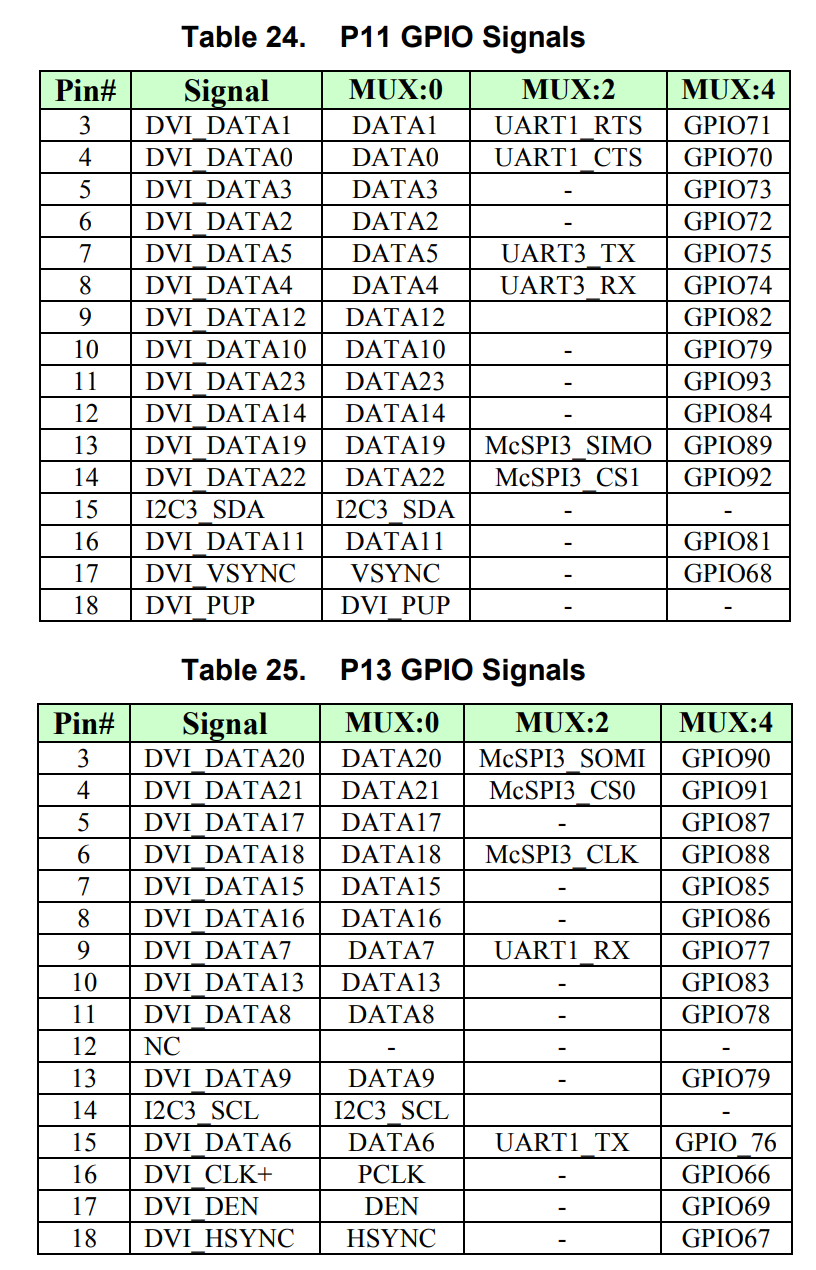
I don’t need DVI output so for example I could use DVI VSync on P11 header to map on GPIO68.
Anyway if there is a better chose I could use it.
Thanks for your help.
Using an already configured pins is a pain, so let’s use a free gpio:
Pin 3 on P17: which is: MMC3_DAT2 - AF13 - MODE 4 - GPIO0_20
Looking at: DM3730 data sheet, product information and support | TI.com
etk_d6.gpio_20 → 0x4800 25E8
CONTROL_PADCONF_ETK_D6[15:0] 0x4800 25E8 etk_d6
CONTROL_PADCONF_ETK_D6 RW 32 0x0000 05B8 0x4800 25E8
gpio_pins: pinmux_gpio_pins {
	pinctrl-single,pins = <
		OMAP3630_CORE2_IOPAD(0x25e8, PIN_OUTPUT | MUX_MODE4)	/* etk_d6.gpio_20 */
	>;
};
Change:
&omap3_pmx_core2 {
	pinctrl-names = "default";
	pinctrl-0 = <
			&hsusb2_2_pins
	>;

	hsusb2_2_pins: pinmux_hsusb2_2_pins {
		pinctrl-single,pins = <
			OMAP3630_CORE2_IOPAD(0x25f0, PIN_OUTPUT | MUX_MODE3)		/* etk_d10.hsusb2_clk */
			OMAP3630_CORE2_IOPAD(0x25f2, PIN_OUTPUT | MUX_MODE3)		/* etk_d11.hsusb2_stp */
			OMAP3630_CORE2_IOPAD(0x25f4, PIN_INPUT_PULLDOWN | MUX_MODE3)	/* etk_d12.hsusb2_dir */
			OMAP3630_CORE2_IOPAD(0x25f6, PIN_INPUT_PULLDOWN | MUX_MODE3)	/* etk_d13.hsusb2_nxt */
			OMAP3630_CORE2_IOPAD(0x25f8, PIN_INPUT_PULLDOWN | MUX_MODE3)	/* etk_d14.hsusb2_data0 */
			OMAP3630_CORE2_IOPAD(0x25fa, PIN_INPUT_PULLDOWN | MUX_MODE3)	/* etk_d15.hsusb2_data1 */
		>;
	};
};
to:
&omap3_pmx_core2 {
	pinctrl-names = "default";
	pinctrl-0 = <
			&hsusb2_2_pins
	>;

	hsusb2_2_pins: pinmux_hsusb2_2_pins {
		pinctrl-single,pins = <
			OMAP3630_CORE2_IOPAD(0x25f0, PIN_OUTPUT | MUX_MODE3)		/* etk_d10.hsusb2_clk */
			OMAP3630_CORE2_IOPAD(0x25f2, PIN_OUTPUT | MUX_MODE3)		/* etk_d11.hsusb2_stp */
			OMAP3630_CORE2_IOPAD(0x25f4, PIN_INPUT_PULLDOWN | MUX_MODE3)	/* etk_d12.hsusb2_dir */
			OMAP3630_CORE2_IOPAD(0x25f6, PIN_INPUT_PULLDOWN | MUX_MODE3)	/* etk_d13.hsusb2_nxt */
			OMAP3630_CORE2_IOPAD(0x25f8, PIN_INPUT_PULLDOWN | MUX_MODE3)	/* etk_d14.hsusb2_data0 */
			OMAP3630_CORE2_IOPAD(0x25fa, PIN_INPUT_PULLDOWN | MUX_MODE3)	/* etk_d15.hsusb2_data1 */
		>;
	};

	gpio_pins: pinmux_gpio_pins {
		pinctrl-single,pins = <
			OMAP3630_CORE2_IOPAD(0x25e8, PIN_OUTPUT | MUX_MODE4)	/* etk_d6.gpio_20 */
		>;
	};
};
Then after this:
	led-controller-2 {
		compatible = "pwm-leds";

		led-3 {
			label = "beagleboard::pmu_stat";
			pwms = <&twl_pwmled 1 7812500>;
			max-brightness = <127>;
		};
	};
I’d add, make sure to uncomment the default state you want…
	led-controller-3 {
		compatible = "gpio-leds";
		pinctrl-names = "default";
		pinctrl-0 = <&gpio_pins>;

		led-4 {
			label = "gpio_20";
			gpios = <&gpio0 20 GPIO_ACTIVE_HIGH>;
			//default-state = "off";
			//default-state = "on";
		};
	};
REgards,
Hello @RobertCNelson,
there is a little error during the compiling phase.
I changed the omap3-beagle-xm.dts according your indications but I have an error:
            *DTC     src/arm/omap3-beagle-xm.dtb*
            *src/arm/omap3-beagle-xm.dtb: ERROR (phandle_references): /led-controller-3/led-4: Reference to non-existent node or label "gpio0"*

            *ERROR: Input tree has errors, aborting (use -f to force output)*
            *make[1]: *** [Makefile:185: src/arm/omap3-beagle-xm.dtb] Error 2*
            *make: *** [Makefile:147: all_arm] Error 2*
I checked the files included by omap3-beagle-xm.dts and found that omap3.dtsi defines some nodes gpiox but there isn’t gpio0 used in the change for etk_d6.gpio_20 so I think I need to add the definition for gpio0
gpio0: gpio@yyyyyyyy {
compatible = “ti,omap3-gpio”;
reg = <0xyyyyyyyy 0xzzz>;
interrupts = <??>;
ti,hwmods = “gpio0”;
ti,gpio-always-on;
gpio-controller;
#gpio-cells = <2>;
interrupt-controller;
#interrupt-cells = <2>;
};
Is it correct?
How can I complete the gpio node definition?
Many Thanks!
Maybe it’s off by one… ?omap3.dtsi « dts « boot « arm « arch - kernel/git/torvalds/linux.git - Linux kernel source tree
gpio1…
omap3 came out before the move to device-tree’s, so things are not always a one for one match…
Edit, yeah it’s off by one: omap3-gta04.dtsi « dts « boot « arm « arch - kernel/git/torvalds/linux.git - Linux kernel source tree and omap3-gta04.dtsi « dts « boot « arm « arch - kernel/git/torvalds/linux.git - Linux kernel source tree
gpios = <&gpio1 7 GPIO_ACTIVE_HIGH>;
OMAP3_WKUP_IOPAD(0x2a14, PIN_INPUT | PIN_OFF_WAKEUPENABLE | MUX_MODE4) /* sys_boot5.gpio_7 */
Regards,