Code Downloads
Capacitive Sensing Pmod Controller (top-level file): pmod_cdc_ad7156.vhd (15.6 KB)
I2C Master (must also be included in the project): i2c_master.vhd (14.1 KB)
Features
- VHDL source code of a streamlined interface to Digilent’s Pmod CDC1 (Pmod for Analog Devices AD7156 Capacitance-to-Digital Converter)
- Continually outputs latest capacitance data for each channel on parallel interfaces
- Handles I2C communication and all data retrieval from the Capacitance Converter Pmod
- Provides for optional user-defined configuration of the AD7156 capacitance converter
- Configurable system clock rate
Introduction
This details a VHDL component that handles interfacing to Digilent’s Capacitive Sensing AD7156 Pmod, shown in Figure 1. Figure 2 illustrates a typical example of this Capacitive Sensing Pmod Controller integrated into a system. As shown, this Cap Sense Pmod Controller connects to the Pmod ports and executes transactions to configure the capacitance converter and gather data. The data is continually updated and presented on simple parallel interfaces which can be connected to user logic or to output ports on the FPGA.

Figure 1. Digilent Capacitive Sensing AD7156 Pmod

Figure 2. Example Implementation
Background
The Analog Devices AD7156 is a 2-channel capacitance-to-digital converter, featuring both a fixed threshold mode and a mode with adaptive environmental compensation.
Theory of Operation
The Capacitive Sensing Pmod Controller consists primarily of a state machine and an I2C Master component.
State Machine
The design uses the state machine depicted in Figure 3 to implement its operation. Upon start-up the component immediately enters the start state. It remains in this state for 100ms to ensure the Pmod has ample time to power-up. It then proceeds to the configure state, where it configures the capacitance converter’s modes, thresholds, sensitivity, etc. according to user-changeable values. The pause state inserts a 1.3us “Bus-Free Time” between I2C transactions as required in the AD7156 datasheet. In the following read_data state, it gathers the most recent capacitance data from the Pmod’s capacitance converter. Finally, it outputs all data in the output_result state. It then continuously cycles between the pause, read_data, and output_result states to keep the capacitance data regularly updated. Although not shown, resetting the component at any time returns it to the start state.
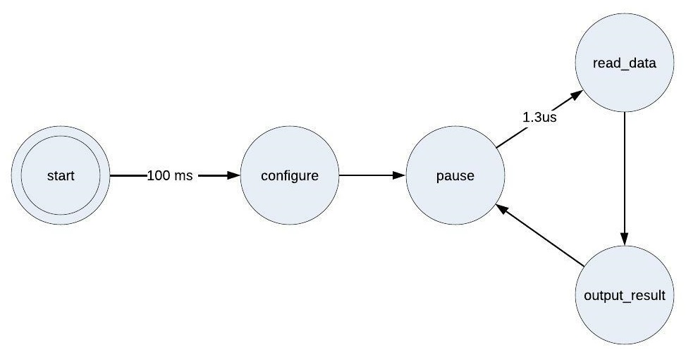
Figure 3. State Diagram
I2C Master
During the configure and read_data states, the state machine controls an I2C Master component to communicate with the capacitance converter on the Pmod. Documentation for the I2C Master is available here.
Configuring the Capacitive Sensing Pmod Controller
The Capacitive Sensing Pmod Controller is configured by setting the generic parameters in the entity.
System Clock Frequency
The generic parameter sys_clk_freq must be set to the frequency of the system clock provided to the Capacitive Sensing Pmod Controller on its clk port.
AD7156 Configuration
The Capacitive Sensing Pmod Controller has seven generic parameters that correspond to seven registers within the AD7156, as listed in Table 1. The values assigned to these generic parameters are written to the registers during the configure state. The default values in the code are the same as the factory default register values. The AD7156 Datasheet (527.3 KB) describes each register bit, so the user can configure the converter as desired.
Table 1. Generic Parameter to AD7156 Register Map for configuration

Port Descriptions
Table 2 describes the Capacitive Sensing Pmod Controller’s ports.
Table 2. Port Descriptions

Connections
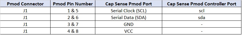
This Pmod has an 8-pin connector. Table 3 provides the pinout for this connector. The Capacitive Sensing Pmod Controller’s ports need to be assigned to the FPGA pins that are routed to this connector as listed. The two rows of the J1 connector are tied together on the Pmod board, so only one side needs to be connected to the FPGA.
Table 3. Capacitive Sensing Pmod Pinout and Connections to Capacitive Sensing Pmod Controller
Reset
The reset_n input port must have a logic high for the Capacitive Sensing Pmod Controller component to operate. A low logic level on this port asynchronously resets the component. During reset, the component aborts the current transaction with the Pmod and clears the cdc_ch1_data, cdc_ch2_data, cdc_ch1_avg, and cdc_ch2_avg data outputs and the i2c_ack_err output. Once released from reset, the Capacitive Sensing Pmod Controller restarts its operation. It reconfigures the capacitance converter and resumes collecting and outputting capacitance data.
Conclusion
This Capacitive Sensing AD7156 Pmod Controller is a programmable logic component that interfaces to Digilent’s Pmod CDC1 (Capacitive Sensing AD7156 Pmod). It handles all communication with this Pmod to configure the Pmod’s capacitance converter and provide a continual stream of updated capacitance data on parallel outputs.
Additional Information
AD7156 Datasheet (527.3 KB)