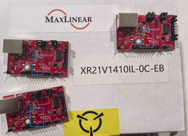
If you are experiencing issues related to jumper wire configuration discrepancies on the XR21V1410IL-0C-EB evaluation board (EVK) compared to the data available on MaxLinear’s official website, please note the following:
The concern specifically involves the 4th pin (RTS#) and its connection to the pull-up resistor and pin header. Unlike what is shown in the product documentation, the 4th pin on the actual board is not connected to a pull-up resistor or the pin header. Instead, it is directly connected to 3.3V (3V3).
Regarding this issue, please check the below details provided by the manufacturer:
Response from MaxLinear :
In revision 1.x , the board has an error: RTS# pin is connected to CTS# pin. therefore, we did a hardware fix to the board.
The EVK and schematic has been corrected. But the gerber file has not (yet).
Please refer to schematic and EVK user manual shown on the following link:
https://www.maxlinear.com/Document/index?id=23253&languageid=1033&type=User%20Guides%20%26%20Manuals&partnumber=XR21V1410
Technical Recommendations :
For EVK testing, please keep original board setting, for your board design, it depends on your application.
If you use the CDC-ACM driver, CTS pin should be pulled down to avoid TX failure due to hardware flow control enabled by default. (Refer to Table 1 of datasheet)
Applicable Part Numbers
| DigiKey Part Number | Manufacturer Part Number |
|---|---|
| 1016-1424-ND | XR21V1410IL-0B-EB |
| 1016-1425-ND | XR21V1410IL-0C-EB |
| 1016-1299-ND | XR21V1410IL-0A-EB |
| 1016-1300-ND | XR21V1410IL16-F |
| XR21V1410IL16TR-F-ND | XR21V1410IL16TR-F |
| XR21V1410IL16MTR-F-ND | XR21V1410IL16MTR-F |