


Hi,
I’m using the IC FUSB302MPX, and its interrupt is given to GPIO of processor which can be configured and Edge triggered only. So can this FUSB302MPX IC interrupt pin support edge trigger?
Regards,
Kaushal
Hello @kaushal.chandrasheka,
Thank you for posting to the DigiKey forum!
One moment please while I work on your request.
Thank you,
Victoria
According to the datasheet on page 4, the INT_N pin can support processor interrupts. The Open-Drain Output means can it perform an edge trigger.

Thank you,
Victoria
Hi
But the driver of FUSG302MPX is level trigger and when we manually change it to edge trigger interrupt is not able to generate. If there is any other change required while manually changing it to edge trigger please assist ASAP.
Regards,
Kaushal
First things first, as Victoria pointed out, INT_N is open-drain. Can you confirm you are using a pull-up resistor?
If so, then moving on to what you say:
I’m struggling to understand this. What is this driver, where is it running, and what exactly are you changing? Are you implying that it was working before you made the change? And if so, why are you changing it?
It sounds to me like you might need help configuring the external interrupt on your processor. If so, it would help if you shared what processor you are using, the relevant source code, and possibly a schematic.
Thanks,
Matt
Hi @Matt_Mielke
Yes there is Pull-up resistor hardware wise.
the driver i’m referring is available in linux source under below mentioned path
“drivers/usb/typec/tcpm/fusb302.c”
Here i’m changing irq properites from
    ret = request_irq(chip->gpio_int_n_irq, fusb302_irq_intn,
                      IRQF_ONESHOT | IRQF_TRIGGER_LOW,
                      "fsc_interrupt_int_n", chip);
to
ret = request_irq(chip->gpio_int_n_irq, fusb302_irq_intn,
IRQF_ONESHOT | IRQF_TRIGGER_FALLING,
“fsc_interrupt_int_n”, chip);
We are using DRA821 Ti Processor, since gpio IP of this CPU does not support level trigger, we need to configure FUSB302 irq as edge triggered.
We observed in different CPU which supports level trigger FUSB302 is able to generate interrupt, but in my current case with edge trigger IRQ is not generating.
Regards,
Kaushal
Thanks, now I understand what you are trying to do.
There are many things that could be going wrong here. Some immediate questions I have are:
- Are interrupts enabled on the processor?
- Are interrupts enabled and properly configured on the FUSB302?
- Have you verified that the FUSB302 is actually generating the interrupt signal?
- Are you sure the device tree is configured properly???
Just to clarify the point, you cannot configure the interrupt signal coming from the FUSB302 as “edge” or “level” triggered. “Triggering” refers to how your processor is configured to read the interrupt signal from an external device, such as the FUSB302, not how the FUSB302 is configured.
If configured for “edge” triggering, this means that your processor will only react to the external signal on a change of state (rising or falling edge, depending on how configured). For example, if your processor is configured for falling-edge triggering, the processor will only react to a falling edge on the interrupt monitoring pin that you designate on the processor. Once it detects a falling edge, it will then trigger an interrupt on your processor. From that point on, it will ignore that pin until it first changes back to a logic high state. Once this occurs, then it can again be triggered when the logic level falls again.
Conversely, if you configure your processor for “level” triggering, it will continuously signal an interrupt as long as the signal on your processor’s interrupt pin remains in the high or low state, depending on which state you configure your processor to detect as a valid interrupt state. When configured as “level” triggering, the pin does not have to change back to the non-trigger state before it can again detect an interrupt.
Hi @Matt_Mielke
Yes, we configured CPU IO for interrupt
Since we are using default driver available in kernel source, hope it takes care irq section
We have verified with oscillator FUSB302 interrupt falls from high to low and doesn’t go back to high state. It will always remain in low
We have configured below fusb as mentioned below in dts
    fusb302: typec-port@22 { / FUSB TypeC /
            compatible = "fcs,fusb302";
            pinctrl-names = "default";
            pinctrl-0 = <&wkup_typec_irq_pins_default>;
            reg = <0x22>;
            fcs,int_n = <&wkup_gpio0 31 IRQ_TYPE_LEVEL_LOW>;
            vbus-supply = <&vcc5v0_typec>;
            status = "okay";
};
Regarding @David_1528
Yes, understood.
We are configuring CPU I/O Pin to edge trigger, we refered FUSB beacuse we configured this interrupt pin under FUSB node in dts
Regards,
Kaushal
I hope it does too, but we should probably make sure. Can you share your complete initialization code for the FUSB302?
Oscillator? Did you mean to type oscilloscope? If not, please explain this further…
Your dts snip isn’t quite what I was expecting. Let me verify, is this the driver you are using? : linux/drivers/usb/typec/tcpm/fusb302.c at master · torvalds/linux · GitHub. If so, it doesn’t appear you’ve met all of the requirements mentioned in the documentation: linux/Documentation/devicetree/bindings/usb/fcs,fusb302.yaml at master · torvalds/linux · GitHub
The interrupt implementation of the FYSB302 is not well explained in the datasheet. I guess the INT_N pin state is NOR function of all non-masked interrupt flags of the chip. That is, INT_N will stay low as long as there is at least one interrupt flag set. That means that there won’t be an edge event at INT_N if all flags are not cleared.
The datasheet does not say how to clear the flags (registers 0x3E, 0x3F, 0x42). If they are cleared by writing 0x00 to the registers, then there is a risk to miss an interrupt event due to race condition (e.g. if a new event occurs between reading the flags and clearing them, the event won’t be recorded).
The bottom line, you can maybe use edge triggered interrupt if you ensure that all the flags are cleared (and consequently INT_N goes high) during the interrupt handling, while keeping in mind that some events may be missed due to probable race issues.
Cheers, heke
Hi @Matt_Mielke
Yes, I meant oscilloscope
Yes we are using same driver.
Yes have met the same requirements but snip was sent only the part of it.
As I interpret the FUSB302 datasheet, to clear an interrupt, one must read the contents of the register which caused the interrupt. Until this time, the interrupt will remain true. So, when your processor detects an interrupt, it should read all registers which can cause an interrupt to determine which one, or ones, actually triggered it. Once that is complete, the interrupt pin, INT_N, will clear.
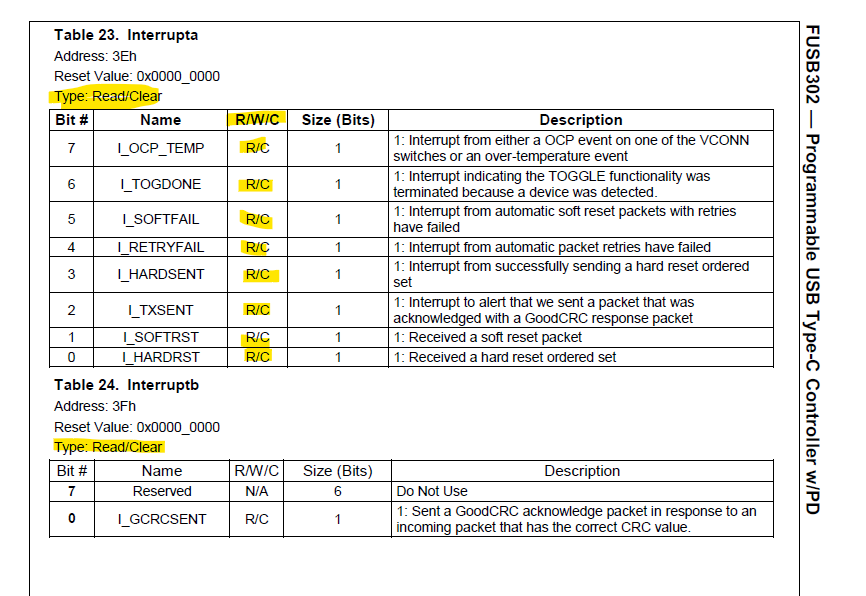
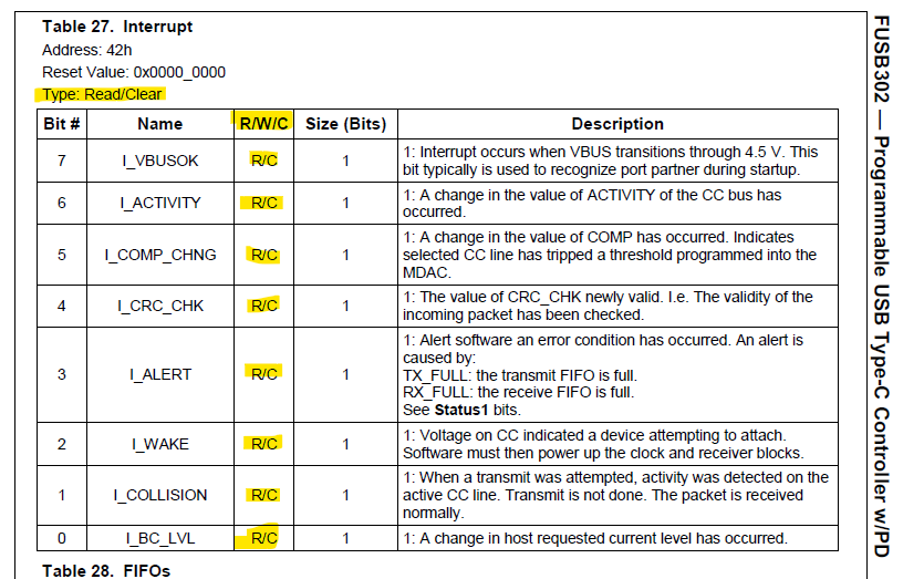
A note on page 6 of the datasheet adds additional backing to this idea:

OK. So can you post the full snip showing that you’ve met the requirements?
Hi @Matt_Mielke
here is the complete snip of code
/ {
        vcc5v0_typec: vcc5v0-typec-regulator {
                compatible = "regulator-fixed";
                regulator-name = "vcc5v0_typec";
                pinctrl-names = "default";
                pinctrl-0 = <&vcc_reg_default>;
                regulator-min-microvolt = <5000000>;
                regulator-max-microvolt = <5000000>;
                gpio = <&gpio0 68 GPIO_ACTIVE_HIGH>;
                off-on-delay-us = <20000>;
                enable-active-high;
        };
};

&usb0 {
        status = "okay";
        dr_mode = "otg";
        usb-role-switch;
        role-switch-default-mode = "none";
        port {
                usb3_drd_sw: endpoint {
                        remote-endpoint = <&typec_dr_sw>;
                };
        };
};

i2c0{
fusb302: typec-port@22 {
                compatible = "fcs,fusb302";
                pinctrl-names = "default";
                pinctrl-0 = <&tcpc_gpio_pins>;
                reg = <0x22>;
                fcs,int_n = <&main_gpio0 8 IRQ_TYPE_EDGE_FALLING>;

                vbus-supply = <&vcc5v0_typec>;
                status = "okay";
                port {
                        typec_dr_sw: endpoint {
                                remote-endpoint = <&usb3_drd_sw>;
                        };
                };
                usb_con: connector {
                        compatible = "usb-c-connector";
                        label = "USB-C";
                        power-role = "dual";
                        data-role = "dual";
                        try-power-role = "sink";
                        source-pdos = <PDO_FIXED(5000, 400, PDO_FIXED_DUAL_ROLE | PDO_FIXED_DATA_SWAP | PDO_FIXED_USB_COMM)>;
                        sink-pdos = <PDO_FIXED(5000, 400, PDO_FIXED_DUAL_ROLE | PDO_FIXED_DATA_SWAP | PDO_FIXED_USB_COMM)>;
                        op-sink-microwatt = <2500000>;
                        ports {
                                #address-cells = <1>;
                                #size-cells = <0>;

                                port@1 {
                                        reg = <1>;
                                        typec_con_ss: endpoint {
                                                remote-endpoint = <&usb3_data_ss>;
                                        };
                                };
                        };
                };
        };
};
But when we configure this GPIO “gpio = <&gpio0 68 GPIO_ACTIVE_HIGH>;” FUSB IC doesn’t generate output. This GPIO is used to enable vbus power. So kindly help us in solving this inerrupt issue.
Regards,
Kaushal


The error message you are receiving is due to the interrupt register failing at some point in the toggle function or within the I2C communication protocol. The issue might be that the VBUS pin is set to high, which is causing problems with the int_n pin being set to falling edge. This configuration may prevent the interrupt register from being cleared in the toggle function.
Which kernel and soc are you using? I’d use IRQ_TYPE_LEVEL_LOW on this
the fusb302 driver is mainline:
		interrupt-parent = <&gpio0>;
		interrupts = <RK_PD3 IRQ_TYPE_LEVEL_LOW>;
Can you share your pimux of main_gpio0 8…
Regards,
We are using TI-DRA821 CPU with L6.1.18, here GPIOs of this CPU doesn’t support level trigger irq.
pinmux details
J721E_IOPAD(0x1c, PIN_INPUT, 7)
So kindly give the solution for edge triggered interrupt using this FUSB IC
Regards,
Kaushal
Do you have a link to a specific errata? Haven’t ran into that with the j721e on the BeagleBone AI64…
J721E_IOPAD(0x1C, PIN_INPUT, 7) /* (AD22) PRG1_PRU0_GPO6.GPIO0_7 */
	interrupt-parent = <&main_gpio0>;
	interrupts = <7 IRQ_TYPE_LEVEL_LOW>;
	interrupt-parent = <&main_gpio0>;
	interrupts = <7 IRQ_TYPE_EDGE_FALLING>;
Please share your exact cpu, device and package name… TI-DRA821 should be using J7200_IOPAD( not J721E_IOPAD( macro’s… What gpio pin are you actually using?
Regards,