As a continuation of my LTSpice series of posts, I will introduce how to make components with editable attributes that can be used for more advanced designs. Please review the following post if you do not know how to make sub-components:
In this post, I will cover making a potentiometer as this item is not yet in the pre-installed library. I would recommend using the hierarchical block method for this example.
Create Circuit With Parameters
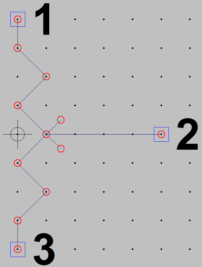
- Create the following circuit with either the same names for the unconnected pins or use significant names for each pin.
- After this, rewrite the value of R1 to {Ra} or something similar. The value has to be different for R2 with the same format (squiggle brackets).
- Add the following SPICE directives to the schematic:
- Create the symbol for this circuit.
- Use the sub-circuit and add values when right-clicking.


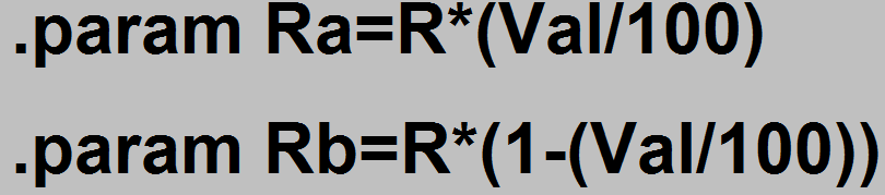
Remember these can be added by pressing the “S” on the keyboard or clicking the .op in the toolbar. What this does is take the parameters Ra and Rb and set them equal to equations. Potentiometers are based off a total resistance split up into two other resistances that add up. The R stands for the total resistance and the Val stands for the number over 100 to make the percentage. So if Val is set at 50, Ra will equal Rb and add up to the total resistance R.
Remember to leave the attributes alone and make sure that Cell type was selected for a Hierarchy part.

Any example circuit can be set up, I chose to use a voltage divider setup to test if the potentiometer works. Right-click the potentiometer to bring up this menu:

The second box that says PARAMS is the one to edit. Add R=AnyNumber, Value= any number between 0 and 100 (not 0 or 100 including). The comma separates parameters. R can be any value of resistance and can even include the shorthand values for metric (K,m,n,u, Meg, etc…). Unlike real potentiometers, the theoretical model cannot reach 0 and cannot reach 100 where all potentiometers can reach their min and max values. You can approximate by entering values really close to 100 or really close to 0 through decimals. Click the checkbox next to PARAMS if you want the parameters visible on the schematic.

After that, values can be easily changed by only changing Val as there are plenty of positions between 0 and 1K in my example.