Selection of voltage protection & step down components

I’m just wondering if I could get a little help selecting a couple of components please.

What I’m trying to achieve:

Scenario 1:

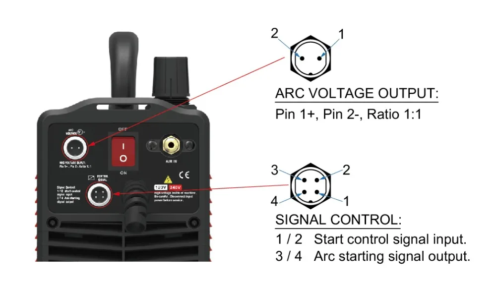
Voltage divider to act as a bridge between the cnc port on my plasma cutter and an arduino to control this. I understand the voltage ranges from the plasma cutter will be somewhere between 100-200v, and I need to step this down to somewhere between 5-12v so my arduino can read this without frying it, to act as a torch height controller.

The plasma unit itself can put out upto 45-55A, but would normally be around 30-40A, however I’m unsure if it would put this amperage out through the CNC port.

What would be a product could achieve this ?
I understand that something like this component below might be suitable if it wasn’t for the amperage requirement: https://www.digikey.com.au/product-detail/en/linear-technology-analog-devices/LT8315EFE-PBF/LT8315EFE-PBF-ND/6670433

It is suitable for DC output or only AC ? (Plasma Cutter is inverter DC)

Scenario 2 (Separate project):

I’m linking lithium ion batteries together in series and then in parallel, up-to a dc motor.

Being Li-Ion I would like to add additional protection so no / little current flows back into the batteries to create a short, especially being hooked up to a motor and and another parallel pack.

I will be adding 2x 20.2v lithium packs together to make a 40.4v pack, then i will be linking this up in parallel with an identical pack to form a ‘power rail’ that both of the dc motors can feed off to ensure it is always supplying the same current and voltage to both motors.

Each battery pack is capable of supplying 15A, so there will be about a 30A capacity flowing through the power rail at 40.4v (which will feed into a step down converter to tune it down to 36v for the motor).

Would this product suit this requirement? https://www.digikey.com.au/product-detail/en/stmicroelectronics/FERD40H100STS/497-16954-ND/6166879

Would there be any other considerations I would need to take into account for this scenario?
Are the diodes in the right spots / required in each segment?

I appreciate your help in advance.

For the first problem, there is a point that I should ask. If the plasma cutter is an inverter, it would not be a DC output but an AC output. Inverters convert DC power into AC power, so I would assume that you are getting a 100-200V AC output (you can check with an oscilloscope if you have to that is rated for 100-200V). So if it was an AC output, you would need a AC to DC converter that can take it down to 5V (not 12V). The arduino’s inputs cannot handle 12V, they are limited to around 5V. If your plasma cutter acts as a AC rectifier, then it would turn AC into DC already and you’d get a DC output. You’d need a DC to DC converter capable of taking your output down to 5V for the input. One other note, the Arduino might not care if the current is regulated or not, so if the system outputs a DC signal, you’d just need two resistors instead of a converter, not one resistor seen in your schematic. Following Kirchoff’s voltage law, voltages added up in a complete circuit loop must equal 0, the voltage after the one resistor would be 0 volts. You need a second resistor to split off the voltage (between ground and the first resistor). Since your plasma cutter is acting as a power supply, the current output is just the maximum, so anything being attached to the output will only draw what the load measures. Meaning you only need to change the voltage level (in theory).

As for the second project, you have too many “unnecessary” diodes placed. You really only need two diodes in the circuit, not four. The batteries can stay in series without a diode between them, just don’t reverse polarities. The diode after the battery will almost eliminate 100% of the potential reverse current. You’d expect very small leakage if any in this application.

The plasma cutter plugs into an AC powerpoint and converts this into DC for its internal workings / torch, so anything the cutter outputs is DC. So I would just need a DC -> DC step down converter, i know this much. The plasma cutter is this one: ArcSonic Herocut55 Plasma Cutter

Some plasma cutters already have a voltage divider in them, usually about 1:16 from memory, its just unfortunate mine outputs 1:1, leaving me to deal with the high voltage problem.

As per the above picture it has 2 ports to feed out the voltage then other ports i believe where i can send the signal back in to control the torch.

I think the required circuit you’ve described is something like this ? http://everycircuit.com/circuit/4677295042985984

I haven’t found any components on here that would handle that kind of power, which is where I would need help.

I appreciate your help in advance.

1 Like