The microblower made by Murata (Digi-Key P/N 490-5856-ND) requires a “driver” that apparently Murata does not make. Do you sell a driver for the 490-5856-ND microblower (and/or P/N 490-MZB3004T04-ND and/or P/N 490-MZB3005T06-ND)
Hi bkozak,
Welcome to the Tech Forum. We do not sell a specific driver for this blower, but I did find a schematic for a recommended driver circuit.

I had already found this sketch. Any suggestions for a manufacturer who could make a few of these boards?
We do offer a board manufacturing service at Digi-Key.
Click here for info on DKRed.
If you can design the board, you can have the empty boards made at DKRed.
You would just have to solder all the components onto it.
Hello, I think I can help you with this.
Good Afternoon Houari,
I forwarded your earlier email to the Precision Fermentation engineer who actually works on our boards. I will let you know what he wants to do. My role is to integrate the instruments, pumps, valves, etc. to get the desired result and to lead the development / testing / commercialization. However, I don’t get personally involved in board design.
Bill Kozak
Consultant
Precision Fermentation
248-835-5414
Hello,
I too was able to find the schematic that was posted earlier on this thread, and discovered that it was able to drive P/N MZB1001T02, as listed at the top of the schematic. I was able to purchase an “eval kit” from here.
Unfortunately, the same circuit does not appear to drive P/N MZB3004T04. On looking at the datasheet, the resonant frequency of the MZB1001 is 24.0 to 27.0kHz. The resonant frequency for the MZB3004 is listed as 21.5 to 24.5 kHz. My guess is that the driver board is oscillating at a higher frequency than the MZB3004 will resonate at. Maybe the frequency can be changed by swapping out some of the components?
There is a different schematic on the datasheet for the MZB3004:
if the image isn't great, the datasheet can be downloaded from DigiKey's site. The schematic is on pg. 14. Fair warning - it's not much clearer.
I’m having a hard time reading/deciphering the labels, particularly at the top left corner of the screen, on Q1. The way I read it, the voltage source (I think) at the top left is Vs, and the other voltage, at the bottom right, is Vc.
The only way I can make sense of this is that the Vs is where the DC 8-18V is applied, and the Vc is routed to the rest of the schematic, but I can’t be sure because the schematic is so fuzzy.
I recreated the schematic as best I could using Altium. Here’s a PDF of the schematic I created.
MZB3004T04 Driver.pdf (56.9 KB)
Has anyone built this schematic or successfully used the MZB3004T04 microblower? If so, can you please explain/clarify the schematic?
Thanks
Agreed. My guess is it’s meant as a soft-start network of some kind. At a glance, it would appear that amps A & B are basically pre-drivers for the BJTs, amp C looks like some sort of current monitor/feedback/level control, and the network around amp B is responsible for the phase shift necessary to produce oscillation. I’d suggest dropping it into LTspice or other simulator of choice for closer study.
Hi all,
I think Rick’s explanation is accurate. Actually, amp B is a high-Q band-pass filter, which is a bit strange choice, as then the circuit is much less fail-safe. E.g. If the center frequency of the filter is too much off, or the supply voltage is too low, then the circuit won’t oscillate and that may damage the microblower.
Cheers,
heke, AsamaLab
Update:
I created a board layout based on the schematic I created in Altium, the schematic I created and posted earlier. I received the boards last week (DKRed - not a great experience either - mostly lack of communication) and was able to build one up today. I’ve tested the circuit 2 different ways, by applying power to Vin and GND at 10VDC, with a 100mA current limit. This clamped the supply to ~7VDC with no signs of life from the microblower. Applying power to Vs and GND had a similar result, clamping the supply to ~0.7VDC.
I’ve had no success with trying to contact Murata support directly, and the support available through DigiKey global tech support has been very limited, and altogether not useful.
Anyone have any additional insight on how to make this schematic work? Alternatively, is there a way to alter the schematic for the MZB1001 to change its operating frequency to match the MZB3004?
Did you mean Vc? What’s labeled Vin in your schematic is a mid-supply reference, and powering the apparatus at that node wouldn’t be expected to give favorable results.
When the current limiter clamps to one diode drop when trying to power a new circuit, I usually take that as an indication that something’s backwards, that I made an error in layout, or that I planted the wrong part. Take a careful look for silly mistakes and give it another go…
The peak-peak drive applied by the circuit in question appears to be double that developed by the first in the thread, which may have some bearing on things.
1 Like
Thanks for the suggestion. After writing my last post, I checked things over, and noticed that there was an error in the copper. The schematic was laid out correctly, but the pin mapping was wrong on one of the components. (I suppose that’s what you get for having a mechanical engineer do the PCB design/layout ![]() ) I was able to flip the component upside down to make it work this time, and I’ll fix the layout for the next run of boards.
) I was able to flip the component upside down to make it work this time, and I’ll fix the layout for the next run of boards.
Anyway, with that fixed, I have a functional driver board for the MZB3004 microblower. We are feeding 8-18VDC to Vs and GND, and the blower draws 30-60mA in operation.
The next thing I’ve come up against is the need for more airflow, which brings to mind another question (again, mechanical engineer here…). Is this circuit intended to be adaptive - so that it finds the resonant frequency of the particular microblower that it’s connected to, or does the circuit operate at a fixed frequency? Because of the low current draw of a single microblower, I am hoping to be able to drive 2 blowers in parallel to get increased volume flow. Obviously, if each microblower has its own, slightly-different resonant frequency, and the drive electronics “finds home” at the resonant frequency of that particular microblower, this may not be possible. But, if the circuit has a fixed frequency and the microblowers can/will resonate at any frequency in the range stated on the datasheet (21.5 to 24.5 kHz), it seems like I could drive 2 blowers on a single circuit.
Are there any holes in this logic?
The blowers themselves appear to function as part of the the oscillatory mechanism in both instances, so a person’s probably looking at some sort of self-tuning circuit there.
I don’t have much information as to typical spreads of component characteristics, or the influence of operating somewhat off-resonance as a consequence of averaging device characteristics. A person could probably get some useful information empirically, but from a product planning standpoint I wouldn’t bet the farm on being able to happily run more than one on a given drive circuit.
That’s what I figured. Turns out we’ll be able to make a single blower work, so it’s a non-issue anyway.
Thanks for all the help!
I’m back with another issue related to the MZB3004T04 microblower. We have developed a schematic using components equivalent to those on Murata’s datasheet, and have had success with making several copies of the circuit board. Here are the schematic and board layout.

We then happened on an issue where, on application of power, the circuit draws ~20mA (compared to 50-70 during normal operation). At this current, the microblower is not moving air, but is making audible noise. The curious thing is that we have found that using our finger to touch the common node between R19 and R11 (right next to the R19 designator) seems to change things enough (either with resistance or capacitance - not sure which) to allow the microblower to start functioning, and the circuit then draws the normal 50-70mA.
Any explanations/theories as to why this might be happening? Is there something that could/needs to be added to the board in order to accomplish this automatically?
Thanks
The R11/13/19 node is low impedance, so I’m a bit surprised that interaction at that point would get the party started. Other than measuring currents, have you looked at any of the other waveforms to get some idea of what might be going on? As Paul mentioned, it’s not obvious that this circuit does all that might be done to assure proper startup of the oscillator…
Speaking of contact adding resistance inspires question as to between which points, and of adding capacitance, between what nodes. The ubiquitous 50/60Hz signals in the environment and sometimes-sneaky/implicit connection of various power sources to earth ground can cause woe due to being out of sight/mind, but one’s usually talking about interaction with higher-impedance nodes that the output of a half-bridge in such cases.
Rick,
Thanks for the reply. Something else we’ve noticed is that after reflowing all the components on the passive side, and leaving the flux residue on the board (no-clean water-soluble flux), the circuit seems to start oscillating reliably. Once we cleaned the board with water and dried it with ionized air, we came up against the behavior that I described in my previous post. Any suggestions/new revelations?
Thanks again,
Michael
Hello,
I would check the data sheets for all the components used. I looked at MZB1001T02 on this link: https://media.digikey.com/pdf/Data%20Sheets/Murata%20PDFs/MZB1001T02_DS.pdf
They are recommending hand solder. They do not list anything for washing. Usually if that is not listed, it is not recommended. So if all of the compents used are not washable, it can lead to issues. I am not even sure if you have the part on the board , or you are just showing the driver board. This just could provide issues. Just one thing to think about.
Flux residues typically make for higher leakage, but it’s a small effect to start with. That said, it doesn’t take much if one’s talking about the tiny seed needed to start oscillation in an unstable system or nucleate the crystallization of a supercooled fluid, or any other such phenomenon…
One thing I do notice is that the offset spec of the '9364 op amp in your schematic is rather looser than that of the '4197 mentioned in the datasheet example. I could conceive of that factor being a step that must be overcome in order to get the oscillation going, and would be curious what happens if a person were to introduce some delay in one of the mid-supply references to the driver amps to create asymmetry on startup. If a bit of flux residue is enough to start the party, I could imagine that hanging C4 off pin 12 might make enough LC delay with parasitic trace inductance to do the same.
All,
Thanks for the input. Regarding the cleaning/washing, the boards are washed, but the blowers are not. The blowers themselves are attached via flying leads from the holes marked “A” and “B”.
We broke out the scope late yesterday to take a look at the waveforms, and here’s what we found:
Normally running microblower @ ~70mA:

Driver board output @ 20mA - microblower making noise, but no airflow
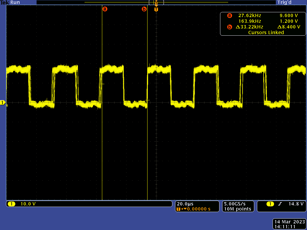
Same as above, after touching R19/R11 with finger:

Below is a link to a video of yet another behavior, where the current starts out at ~20mA, and slowly increases to the normal 60-70mA.
All of these look like the oscillator is able to start, but it seems to start at the wrong frequency (~33kHz instead of the required 21.5-24.5kHz, per the datasheet).
Does this behavior seem like something that would be fixed by making this connection? Or is this a situation where it won’t be clear until/unless we try it?
Thanks again!
Michael