Created by Taylor Roorda, last modified on Jan 04, 2018
Introduction
In the age of Internets and things, there are a lot of mundane projects that can be made more interesting by adding an Internet connection. LED lighting is one such instance. There are a variety of pre-made, commercial solutions such as the Philips Hue for example. Most of these use the Zigbee wireless protocol and require an additional gateway between the device and WiFi router. This project implements a purely WiFi based system using a Particle Photon. The Photon can connect directly to a home WiFi network, eliminating the need for a gateway. Blynk is used to create a customized remote that can be used on Android and iOS devices.
Goals for this project include:
- Create an RGB LED controller that can be controlled from a smartphone over WiFi.
- Have multiple modes for effects such as breathing, color changing, etc.
- Capability to sync the blinking of the LEDs to music from a nearby source.

Required Resources
- Particle Dev IDE - The cloud version, Particle Build, will work as well but I found it easier to work with the desktop version.
- Blynk App
- LED-Controller-Source.zip - Includes KiCad schematic/layout, gerber files, source code, and enclosure STL files.
Bill of Materials
| Qty | Reference | Part Number | Value |
|---|---|---|---|
| 6 | C1, C2, C5, C6, C7, C8 | 445-173583-1-ND | 1u |
| 5 | C3, C9, C10, C11, C12 | 490-8809-ND | 0.1u |
| 1 | C4 | 478-1883-ND | 0.33u |
| 1 | J1 | CP-050AH-ND | Barrel Jack |
| 1 | J2 | S5479-ND | 4 Pos R/A Conn |
| 1 | MK1 | 102-1721-ND | Microphone |
| 3 | Q1, Q2, Q3 | FDP8880FS-ND | NMOS |
| 1 | R1 | 2.2KH-ND | 2.2k |
| 3 | R2, R3, R4 | 10KH-ND | 10k |
| 1 | R5 | 1.0MH-ND | 1M |
| 2 | R6, R7 | 1KH-ND | 1k |
| 1 | R8 | 680QBK-ND | 680 |
| 1 | RV1 | PDB12-H4301-105BF-ND | 1M |
| 1 | U1 | 296-1857-5-ND | TLC555 |
| 1 | U2 | MCP601-I/P-ND | MCP601P |
| 1 | U3 | 1878-1000-ND | Photon Module |
| 1 | U4 | MC78M05CTGOS-ND | MC78M05CDT |
| 3 | U5, U6, U7 | MCP1407-E/AT-ND | MCP1407 |
| 1 | 1647-1035-2-ND | RGB LED reel | |
| 1 | 102-3665-ND | 12V 60W Power Supply | |
| 2 | S6100-ND | 12 Pos 0.1" Female Header | |
| 4 | 1772-1337-ND | #4-40 Hex Standoff 3/16" | |
| 4 | 36-9901-ND | Phillips #4-40 Machine Screw |
Table 1. Bill of materials.
Hardware
As seen in Figure 1 below, there are 3 main parts to the circuit and 4 supplementary sections. Each section is summarized below.
- The upper row is contains the power circuitry.
- 12V is received through the barrel jack and passed through a linear regulator, U4 , and also out to the LED connector.
- In the microphone section:
- The microphone, MK1 , is used to pick up background music which the Photon can use to sync the LEDs.
- Resistors R2 and R3 add a DC bias of ~1.65V to the audio signal.
- R6 and C12 create a low pass filter with a frequency cutoff of 2400 Hz. Since the Photon will sync the LEDs to the “pulse” of the music, only low frequencies (100 - 1 kHz) are required.
- The op amp, U2 , amplifies the signal by a gain dependent on R5 and the pot RV1 . The base gain is set at 1000, but can be increased to 2000 by setting the pot to its max value. Adjust the value of R5 to increase or decrease the sensitivity as necessary.
- The cap, C2 , in the op amp’s feedback path ensures that only the AC component of the signal is amplified while the DC component is unaffected.
- In the bottom left, a 555 timer in astable mode generates a 4.8 kHz square wave that is used to establish the sampling rate for Photon’s ADC.
- The Photon receives the amplified audio signal and a trigger from the 555 timer to set the sampling rate. It also generates the PWM signals for the LEDs.
- The PWM signals from the Photon are passed into the MOSFET drivers, U5, U6, and U7. These drivers allow the gates of the output MOSFETs ( Q1, Q2, Q3 ) to be driven at a higher voltage, decreasing RDSon, while also providing an extra barrier of isolation between the 12V signals of the LEDs and the Photon.

Figure 1. Circuit schematic.
Figure 2 below shows the PCB layout. All components were through hole to make hand assembly easier, but the size could be greatly reduced by using surface mount parts.

Figure 2 . PCB layout.
Blynk Setup
The Blynk remote for this project uses 7 widgets and requires all of the credits available to a free user. The layout is shown in Figure 3 .
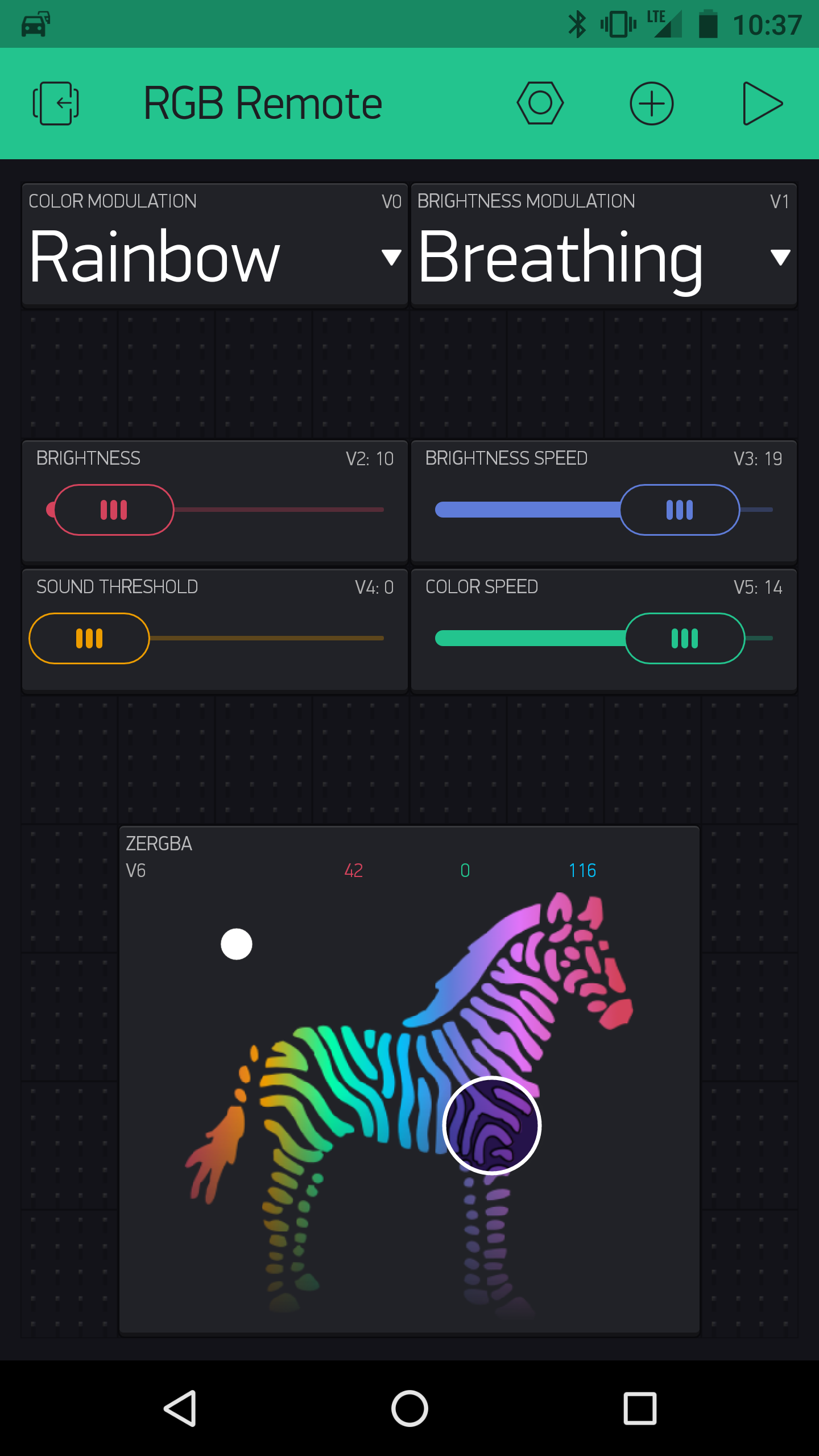
Figure 3. Blynk remote app.
The widget configurations are shown below. Send on release is enabled for all of the widgets to minimize data usage. Each setting is assigned its own virtual pin which will cause a user defined function on the Photon to be called when that setting is changed.
- Color Modulation Menu (V0)
- Constant
- Rainbow - constantly cycles through the color spectrum.
- Brightness Modulation Menu (V1)
- Constant
- Breathing - fades in and out.
- Audio Sync - pulses to the beat of music.
- Brightness Slider (V2)
- Set the maximum overall brightness
- Range : 0 → 100%
- Default : 25%
- Brightness Speed Slider (V3)
- Set rate at which the brightness changes in breathing or audio mode
- Range : 80 → 5 ms
- Default : 30 ms
- Sound Threshold Slider (V4)
- Adjusts the level required to trigger the LEDs in audio mode
- Range : 0 → 2048
- Default : 1500
- Color Speed Slider (V5)
- Set the rate at which the color changes in rainbow mode
- Range : 80 → 5 ms
- Default : 30 ms
- zeRGBa Color Chooser (V6)
- Merge output to a single virtual pin
- Range : 0 → 255 for each color
Software
The full application code for the Photon is found below along with the Octave/Matlab script used to generate the filter coefficient header file. To summarize:
- The application code is run in parallel with the background Particle tasks by using SYSTEM_THREAD(ENABLED) . This allows setup() to run up until the point where it requires a WiFi connection without being blocked.
- The main loop of the RGB controller program simply calls Blynk.run() to get updates from the app. All other processing is performed in the callback functions for the brightness and color timers.
- The BLYNK_WRITE() macros define the actions to take when a change is detected from a widget in the Blynk app as shown in Figure 3.
- update_leds() modifies the PWM duty cycles each time one of the timer callback functions is called.
- get_sample() is called at a rate of ~4800 Hz. When the audio mode is selected, this function will read the ADC and filter the input with a 100th order FIR bandpass filter created with the Octave script below.
- Calculations are performed using fixed point arithmetic with 20 bits of fractional precision. fixed_mult() is used to perform the multiplications and incorporates the extra type casting and shifting required to get the correct result.
rgb_conrtoller.ino.txt (10.2 KB)
rbg_fir.m (1.2 KB)
coeffs.h (818 Bytes)
Enclosure
A simple box was 3D printed to house the PCB. The mounting holes for the board and standoffs are loosely sized for M3 or #4-40 screws. The STL files can be downloaded below.
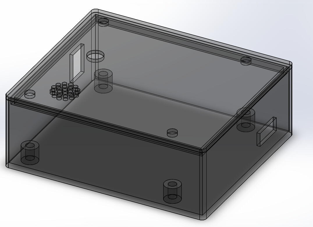
LED-Box-STL.zip (50.7 KB)
Conclusion
This project allows users to set up a relatively simple wireless LED lighting system. The LEDs are controlled using the Blynk app over WiFi. Color and brightness can be adjusted from the app, along with a select few special modes. The system also incorporates a microphone to create an audio syncing effect. These features should create a solid foundation for anyone looking to create their own WiFi-controlled LED system.