In our previous articles, we explored MOSFET drive topologies in MOSFET Drive Topologies in Power Switching and Control and Efficient MOSFET Drive Techniques: Push-Pull and Bootstrap Topologies for High-Speed Switching.
For power electronics applications that require electrical isolation, high-voltage handling, and bidirectional current control, opto-isolated and bridge drive topologies play a critical role. These advanced drive methods help ensure safe and reliable performance in systems like motor drives, inverters, and high-voltage power modules. In this article, we explore the design principles, advantages, limitations, and typical applications of these two advanced drive methods.
1. Opto-Isolated Drive
An opto-isolated drive uses an optocoupler connected to the MOSFET gate to electrically isolate the logic side from the power side, often paired with an isolated gate driver.
It is suitable for industrial control, power modules, motor drives, high-voltage systems (>60V), and safety-critical applications.
Advantages
The advantages of opto-isolated drive include
- Complete galvanic isolation between control and power sides
- Enhanced noise immunity and electrostatic discharge (ESD) protection
- Suitability for high-voltage and harsh environments
Disadvantages
- Increased circuit complexity and cost
- Limitations in transmission delay and bandwidth, depending on the optocoupler’s performance
Design considerations
For opto-isolated drive design,
-
Use dedicated gate-driving optocouplers
Choose optocouplers specifically designed for MOSFET driving, such as onsemi’s FOD3182 or Broadcom’s HCPL-3180, which provide sufficient output current to charge/discharge the MOSFET gate quickly. -
Add a buffer amplifier
If the optocoupler’s output current is insufficient, add a buffer amplifier (e.g., Darlington pair or MOSFET driver IC) to boost drive current. -
Include a gate resistor
Appropriate gate resistors should be designed in. Adding suitable resistors between the output of the optocoupler and the gate of the MOSFET can control the switching speed, reducing oscillation and EMI.
The choice of resistor value needs to strike a balance between switching speed and electromagnetic interference. -
Add a gate pull-down resistor
Adding a pull-down resistor between the gate and source of the MOSFET ensures that the MOSFET remains in the off state when the optocoupler is not conducting, preventing false turn-on due to a floating gate. -
Switching speed of the optocoupler
As the switching speed of the optocoupler will affect the response speed of the entire circuit, an optocoupler with fast rise and fall times should be selected to meet the demands of high frequency switching applications.
Example: FOD3182 opto-isolated MOSFET drive circuit
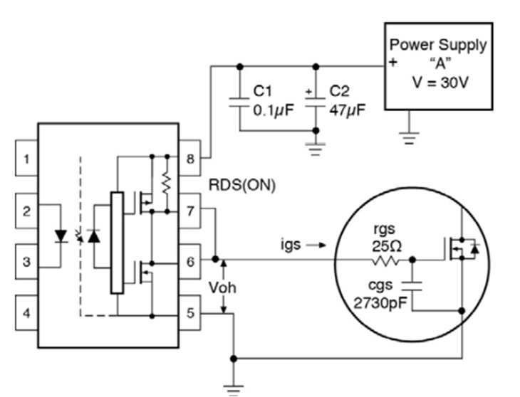
In this configuration, the optocoupler provides isolation and drives the gate through a current-boosting stage. Proper resistor selection and layout practices ensure reliable operation even in noisy or high-voltage environments.
Recommended ICs

Full-Bridge / Half-Bridge Drive
The full-bridge/half-bridge drive structure uses 4 or 2 N-MOSFETs (two (half-bridge) or four (full-bridge) MOSFETs) to control the flow of bidirectional current, commonly found in DC motor forward and reverse control, inverters, UPS systems, etc.
It is suitable for applications such as motor control (DC, stepper), power inverters, and regenerative braking systems.
Advantages
The full-bridge/half-bridge drive has the advantages of,
- Bidirectional control of current flow
- Support for motor forward/reverse control and energy recovery
- High switching efficiency
Disadvantages
- Complex control and Increased design complexity
- The need for precise dead time control
- Requirement for high-side MOSFETs to be bootstrapped or isolated for driving.
Design considerations
In the design of full-bridge/half-bridge drives,
-
1. Prevent shoot-through
In both full-bridge and half-bridge topologies, it is necessary to ensure that the upper and lower MOSFETs do not conduct simultaneously to avoid short-circuiting the power supply, which is typically achieved by setting appropriate dead time. -
2. Use bootstrap drive circuits
The driving of high-side MOSFETs usually relies on bootstrap circuits, so it is important to ensure that the bootstrap capacitor has sufficient capacitance and to select diodes with low forward voltage drop to ensure reliable conduction of the high-side MOSFETs. -
3. Controlled Switching speed
Excessively fast switching can cause electromagnetic interference (EMI) and oscillation. By adjusting the gate resistor values, the switching speed can be controlled to reduce EMI. -
4. PCB layout
Proper PCB layout will help minimize parasitic inductance and capacitance, ensuring the integrity of the drive signals and avoiding EMI issues caused by improper layout.
Example of IR2104 half-bridge drive circuit
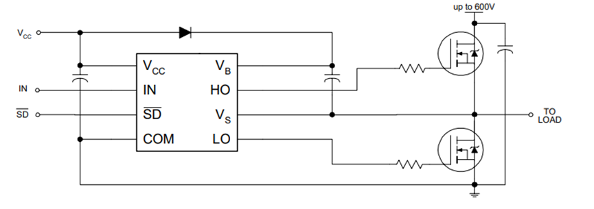
In the example above, the half-bridge drive uses Infineon IR2104 to control high-side and low-side arms with a single input signal, featuring built-in dead time. Select MOSFETs with appropriate switching speed and dead-time compatibility.
Half-bridge drives are commonly used in synchronous DC-DC rectification, while motor control or inverters often use two half-bridges to form a full bridge.

Example of Renesas HIP4080A full-bridge drive circuit

The four bridge arms can be controlled individually by four inputs, or two inputs can be used to control all four bridge arms. If an inverter is added, only one PWM signal is needed to control the four bridge arms, and the dead time can be configured through the DEL pin.
Full bridges are generally used in unidirectional inverters or in driving DC motors that require control of speed and direction.
Drive Topology Comparison Table
| Drive Topology | Applicable Scenarios | Advantages | Disadvantages | Common IC Solutions |
|---|---|---|---|---|
| Optocoupler | High-voltage isolation, motor control, power converters | Electrical isolation, control circuit protection | Slow drive speed, optocoupler speed limits | Broadcom HCPL-3180、onsemi FOD3182 |
| Full/Half Bridge | High-power apps, inverters, DC-AC converters | Bidirectional power control | Precise dead-time control needed | TI DRV8412, Infineon IR2104, Renesas HIP4080A |
Conclusion
After a thorough exploration of various MOSFET circuit design topologies, it becomes clear that selecting the appropriate circuit design topology and mastering the correct design techniques are key to ensuring system stability, switching efficiency, and safety. Whether it is a simple low-side drive or a complex full-bridge circuit, designers must carefully consider factors such as voltage and current specifications, switching frequency, driving capability, and protection mechanisms based on actual application requirements.
Mastering techniques such as bootstrap principles, dead time control, driving current matching, and isolation protection can significantly enhance driving efficiency and effectively extend the lifespan of both the MOSFET and the system.
As power electronics and intelligent control applications continue to expand, MOSFET driving technology will also evolve, bringing more possibilities. Let us make good use of these design techniques to create more efficient, reliable, and intelligent electronic systems!
Related Article
Efficient MOSFET Drive Techniques: Push-Pull and Bootstrap Topologies for High-Speed Switching
MOSFET Drive Topologies in Power Switching and Control
Applicable Part Numbers
| DigiKey Part Number # | Manufacturer Part Number # |
|---|---|
| 516-1675-5-ND | HCPL-3180-300E |
| 516-1674-5-ND | HCPL-3180-000E |
| 516-3778-2-ND,516-3778-1-ND,516-3778-6-ND | HCPL-3180-500E |
| HCPL-3180-ND | HCPL-3180 |
| 516-2712-5-ND | HCPL-3180-060E |
| HCPL-3180-560E-ND | HCPL-3180-560E |
| 516-2713-5-ND | HCPL-3180-360E |
| HCPL-3180-500-ND | HCPL-3180-500 |
| HCPL-3180-300-ND | HCPL-3180-300 |
| HCPL-3180-560-ND | HCPL-3180-560 |
| HCPL-3180-360-ND | HCPL-3180-360 |
| HCPL-3180-060-ND | HCPL-3180-060 |
| FOD3182-ND | FOD3182 |
| FOD3182S-ND | FOD3182S |
| FOD3182SDVTR-ND,FOD3182SDVCT-ND,FOD3182SDVDKR-ND | FOD3182SDV |
| FOD3182SV-ND | FOD3182SV |
| FOD3182V-ND | FOD3182V |
| FOD3182SDTR-ND,FOD3182SDCT-ND,FOD3182SDDKR-ND | FOD3182SD |
| FOD3182TSR2VTR-ND,FOD3182TSR2VCT-ND,FOD3182TSR2VDKR-ND | FOD3182TSR2V |
| FOD3182TV-ND | FOD3182TV |
| FOD3182TSV-ND | FOD3182TSV |
| FOD3182TSR2TR-ND | FOD3182TSR2 |
| IR2104SPBFTR-ND,IR2104SPBFCT-ND,IR2104SPBFDKR-ND | IR2104STRPBF |
| IR2104SPBF-ND | IR2104SPBF |
| IR2104PBF-ND | IR2104PBF |
| IR2104S-ND | IR2104S |
| IR2104-ND | IR2104 |
| IR2104STR-ND | IR2104STR |
| HIP4080AIBZTTR-ND,HIP4080AIBZTCT-ND,HIP4080AIBZTDKR-ND | HIP4080AIBZT |
| HIP4080AIBZ-ND | HIP4080AIBZ |
| HIP4080AIPZ-ND | HIP4080AIPZ |
| HIP4080AIB-ND | HIP4080AIB |
| HIP4080AIP-ND | HIP4080AIP |
| HIP4080AIBT-ND | HIP4080AIBT |
| 296-25561-2-ND,296-25561-1-ND,296-25561-6-ND | DRV8412DDWR |
| 296-33276-5-ND | DRV8412DDW |