Stepper motors , Motor Drivers Technologies: Full-Step, Half-Step, and Microstep Control Modes
This article introduces the full-step mode .
Full-Step Mode
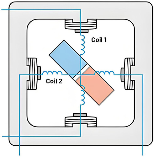
To better understand the stepping behavior of stepper motors, we evaluate a simplified 2-phase stepper motor model with one pair of magnetic poles.
Simplified 2-Phase Stepper Motor with Permanent Magnet Rotor (source: ADI)
Principle
The driver applies positive or negative current to two coils, energizing both phases simultaneously to achieve maximum torque. By switching the current direction in the coils, the motor shaft rotates at a fixed step angle, following a specific commutation sequence:
- Coil 1 = +I, Coil 2 = +I
- Coil 1 = -I, Coil 2 = +I
- Coil 1 = -I, Coil 2 = -I
- Coil 1 = +I, Coil 2 = -I
Full-Step Mode of 2-Phase Stepper Motor (ADI source)
The figure above shows four different states of a 2-phase stepper motor in full-step mode. In each state, the energization of the coils corresponds to the current multiples above, and the position changes of the rotor (blue and orange parts) under different energization states visually demonstrate the operating principle of the full-step mode.
In the first step, the current multiples for Coil 1 and Coil 2 are both 1. In the second step, Coil 1’s current multiple becomes -1 while Coil 2 remains at 1, and so on, showing periodic changes.
Performance Advantages and Limitations
- Advantages:
- Achieves precise step angles, speed control, and high holding torque.
- Maximizes torque output at high speeds.
- Limitations:
- Large step angles cause obvious positional jumps during operation, leading to high resonance, overshoot (rotor exceeding the target position), and reduced actual applied torque.
- Generates vibration and noise, which may pose issues in applications requiring high precision and stability.
Overshoot and Oscillation in Full-Step Operation (ADI source)
As shown above, the full-step mode exhibits periodic step-like changes. Noticeable overshoot (position exceeding the expected stable position) and ringing (position fluctuating around the stable position) occur during each full-step switch. For example, when switching from the first step to the second, the rotor position first rises rapidly beyond the stable position of the second step and then oscillates around it before gradually stabilizing.
Related Products
TMC2240 and TMC5240 are intelligent, high performance 2-phase stepper motor driver ICs integrated with motion controllers. The 8-point motion ramp function simplifies the system architecture, allowing users to easily program desired positions and motion profiles.
TMC2160 and TMC5160 are high power 2-phase stepper motor driver ICs supporting 256 microstep resolution and MicroPlyer microstep interpolation. They optimize driver performance using multiple Trinamic technologies, suitable for a wide range of scenarios from battery-powered systems to high-voltage industrial applications.
TMC2300 is a low voltage driver designed for 2-phase battery-powered stepper motors, featuring 256 microstep resolution and functions such as CoolStep, StealthChop2, StallGuard4, and SpreadCycle.
More contents:
- Basics of Stepper Motor Drive - Motor Structure and Working Mechanism
- Basics of Stepper Motor Drive - Full - Step Mode
- Basics of Stepper Motor Drive - Half - Step Mode
- Basics of Stepper Motor Drive - Microstep Control Mode
- Basics of Stepper Motor Drive - Advantages and Disadvantages of Full - Step, Half - Step, Microstep


