이번 디지키 커피 컵 데모의 목적은 저전력에 최적화된 60nm 공정의 인텔® Cyclone® 10 LP FPGA 평가 키트에서 USB 가상 JTAG 인터페이스를 구현하는 방법을 시연하는 것입니다.
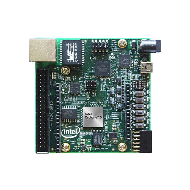
Cyclone® 10 LP FPGA 평가 키트는 저가형인 Cyclone® 10 LP FPGA 소자의 성능과 특성을 손쉽게 확인할 수 있는 매우 사용하기 쉬운 플랫폼입니다. 이 평가 키트에는 다음과 같은 부품들이 사용되었습니다.
주요 탑재 소자
- Cyclone 10 LP FPGA (10CL025, U256 패키지)
- Enpirion EN5329QI/EN5339QI - 2 A / 3 A PowerSoC, 인덕터가 내장된 높이가 낮은 동기식 벅 DC-DC 컨버터
- Enpirion EP5358xUI - 600 mA PowerSoC, 인덕터가 내장된 DC-DC 스텝다운 컨버터
- Altera® XWAY PHY11G 기가비트 이더넷 파이 (PEF7071)
- MAX® 10 FPGA 10M08SAU169C8G - 인텔® FPGA 다운로드 케이블 II 및 시스템 관리 기능 내장
프로그래밍 및 설정
- 인텔 FPGA 다운로드 케이블 II (JTAG) 내장
- 10핀 헤더를 통한 JTAG 직접 연결 옵션
- EPCQ 또는 EPCQ‑A 플래시로부터 Active Serial x1 방식 설정 지원
메모리 장치
- Synaptic Labs에서 제공하는 HBMC(HyperBus Memory Controller) IP가 포함된 128 Mb 8비트 HyperRAM
- 플래시 메모리
- Rev A1 보드: 64 Mb EPCQ
- Rev A2 보드: 128 Mb EPCQ‑A
통신 포트
- 기가비트 이더넷 (GbE) RJ‑45 포트 1개
- 2×20 GPIO 확장 헤더 1개
- 아두이노 우노 R3 타입 커넥터 1개
- 12핀 Digilent Pmod 호환 커넥터 1개
클록 회로
- Silicon Labs Si510 50 MHz 수정 발진기
- Silicon Labs Si5351 클록 생성기 - GUI를 통한 주파수 프로그래밍 가능
전원 공급
- USB Y‑케이블 (USB 타입‑A → 미니 타입‑B) - 온보드 인텔® FPGA 다운로드 케이블 II 및 USB 포트로부터의 5 V 전원 공급용
- 보조 5 V DC 전원 어댑터 옵션 (5 V 전원 어댑터 및 전원 케이블은 키트에 포함되지 않음)
이 링크에서 올바른 FPGA 개발 소프트웨어를 다운로드하고 설치합니다.
Quartus® Prime Lite 설치를 완료하고 Quartus 프로젝트에서 vJTAG (Virtual JTAG, 가상 JTAG) IP 코어도 사용한 상태에서 blink.tcl 이라는 이름의 플랫폼 정의 파일을 사용하여 다음 절차를 진행하십시오.
# File: blink.tcl

# Load Quartus Prime Tcl Project package
package require ::quartus::project

set need_to_close_project 0
set make_assignments 1

# Check that the right project is open
if {[is_project_open]} {
	if {[string compare $quartus(project) "blink"]} {
		puts "Project blink is not open"
		set make_assignments 0
	}
} else {
	# Only open if not already open
	if {[project_exists blink]} {
		project_open -revision blink blink
	} else {
		project_new -revision blink blink
	}
	set need_to_close_project 1
}

# Make assignments
if {$make_assignments} {
	set_global_assignment -name FAMILY "Cyclone 10 LP"
	set_global_assignment -name DEVICE 10CL025YU256I7G
    set_global_assignment -name TOP_LEVEL_ENTITY "blink"
	set_global_assignment -name ORIGINAL_QUARTUS_VERSION 24.1STD.0
	set_global_assignment -name PROJECT_CREATION_TIME_DATE "20:12:02  November, 19 2025"
	set_global_assignment -name LAST_QUARTUS_VERSION "24.1std.0 Lite Edition"
	set_global_assignment -name PROJECT_OUTPUT_DIRECTORY output_files
	set_global_assignment -name MIN_CORE_JUNCTION_TEMP "-40"
	set_global_assignment -name MAX_CORE_JUNCTION_TEMP 100
	set_global_assignment -name ERROR_CHECK_FREQUENCY_DIVISOR 1
	set_global_assignment -name VERILOG_FILE blink.v
    set_global_assignment -name VHDL_FILE jtag.vhd
    set_global_assignment -name VERILOG_FILE vjtag/synthesis/vjtag.v -library vjtag
	set_global_assignment -name PARTITION_NETLIST_TYPE SOURCE -section_id Top
	set_global_assignment -name PARTITION_FITTER_PRESERVATION_LEVEL PLACEMENT_AND_ROUTING -section_id Top
	set_global_assignment -name PARTITION_COLOR 16764057 -section_id Top
	set_global_assignment -name SDC_FILE SDC1.sdc

	set_location_assignment PIN_L14 -to LED0
    set_instance_assignment -name IO_STANDARD "3.3-V LVTTL" -to LED0
    set_location_assignment PIN_K15 -to LED1
    set_instance_assignment -name IO_STANDARD "3.3-V LVTTL" -to LED1
    set_location_assignment PIN_J14 -to LED2
    set_instance_assignment -name IO_STANDARD "3.3-V LVTTL" -to LED2
    set_location_assignment PIN_J13 -to LED3
    set_instance_assignment -name IO_STANDARD "3.3-V LVTTL" -to LED3
	set_location_assignment PIN_E1 -to clk
    set_instance_assignment -name IO_STANDARD "3.3-V LVTTL" -to clk
	set_location_assignment PIN_E15 -to KEY0
	set_instance_assignment -name IO_STANDARD "3.3-V LVTTL" -to KEY0
    set_location_assignment PIN_F14 -to KEY1
	set_instance_assignment -name IO_STANDARD "3.3-V LVTTL" -to KEY1
    set_location_assignment PIN_C11 -to KEY2
	set_instance_assignment -name IO_STANDARD "3.3-V LVTTL" -to KEY2
    set_location_assignment PIN_D9 -to KEY3
	set_instance_assignment -name IO_STANDARD "3.3-V LVTTL" -to KEY3


    set_location_assignment PIN_M16 -to DIP0
	set_instance_assignment -name IO_STANDARD "3.3-V LVTTL" -to DIP0
    set_location_assignment PIN_A8 -to DIP1
	set_instance_assignment -name IO_STANDARD "3.3-V LVTTL" -to DIP1
    set_location_assignment PIN_A9 -to DIP2
	set_instance_assignment -name IO_STANDARD "3.3-V LVTTL" -to DIP2

	set_instance_assignment -name PARTITION_HIERARCHY root_partition -to | -section_id Top

	# Commit assignments
	export_assignments

	# Close project
	if {$need_to_close_project} {
		project_close
	}
}
blink.tcl 파일은 모든 관련 HDL 파일 뿐만 아니라 Cyclone® 10 LP FPGA 외부로 연결되는 모든 적용 가능한 신호들도 정의합니다. 이 가상 JTAG 데모에서는 Cyclone® 10 LP FPGA 평가 키트의 KEY3을 비동기 리셋 입력으로 LED0과 LED1을 출력으로 사용할 것입니다. 그리고 폴더에 다음의 설계 제약 조건 파일인 SDC1.sdc도 추가합니다.
# inform Quartus that the clk port brings a 50MHz clock into our design so
# that timing closure on our design can be analyzed
create_clock -name clk -period "50MHz" [get_ports clk]
# inform Quartus that the LED output port has no critical timing requirements
# it’s a single output port driving an LED, there are no timing relationships
# that are critical for this
set_false_path -from * -to [get_ports LED]
이제 베릴로그 HDL로 작성된 blink.v 파일을 다음과 같이 최상위 계층 (Top Module) 파일로 정의합니다.
// Digikey Coffee Cup Virtual JTAG interface demonstration for Cyclone 10 board

module blink (
    input wire clk, // 50MHz input clock
    input wire DIP0, // input DIP SWITCH 0
    input wire DIP1, // input DIP SWITCH 1
    input wire DIP2, // input DIP SWITCH 2
    input wire KEY0, // input KEY SWITCH 0
    input wire KEY1, // input KEY SWITCH 1
    input wire KEY2, // input KEY SWITCH 2
    input wire KEY3, // input KEY SWITCH 3
    output wire LED0, // LED0 output
    output wire LED1, // LED1 output
    output wire LED2, // LED2 output
    output wire LED3 // LED3 output
);


    //=======================================================
    //  vJTAG
    //=======================================================
    wire tdi, tdo, tck, v_cdr, v_sdr, v_udr;
    wire [3:0] ir_in;
	vjtag u0 (
		.tdi                (tdi),                // jtag.tdi
		.tdo                (tdo),                //     .tdo
		.ir_in              (ir_in),              //     .ir_in
		.ir_out             (),             //     .ir_out
		.virtual_state_cdr  (v_cdr),  //     .virtual_state_cdr
		.virtual_state_sdr  (v_sdr),  //     .virtual_state_sdr
		.virtual_state_e1dr (), //     .virtual_state_e1dr
		.virtual_state_pdr  (),  //     .virtual_state_pdr
		.virtual_state_e2dr (), //     .virtual_state_e2dr
		.virtual_state_udr  (v_udr),  //     .virtual_state_udr
		.virtual_state_cir  (),  //     .virtual_state_cir
		.virtual_state_uir  (),  //     .virtual_state_uir
		.tck                (tck)                 //  tck.clk
	);

    //=======================================================
    //  jtag control
    //=======================================================
    reg d0, d1;
    wire bypass_state, write_state, read_state;
    jtag #(.JTAG_BYPASS("0000"),.JTAG_READ("0001"),.JTAG_WRITE("0010")) jtag_inst  (

	//Reset
    .aclr(~KEY3),

	//vJTAG interface
	.tdi(tdi),
	.tdo(tdo),
	.ir_in(ir_in),
	.v_cdr(v_cdr),
	.v_sdr(v_sdr),
	.v_udr(v_udr),
	.tck(tck),

    //leds
    .d0(LED0), .d1(LED1)

 );

endmodule
그리고 디지키는 VHDL HDL로 작성한 간단한 커피 컵 버전의 가상 JTAG 인터페이스 파일도 개발하였습니다.
-- DigiKey Coffee Cup Virtual JTAG

library ieee;
use ieee.std_logic_1164.all;
use ieee.numeric_std.all;
use ieee.math_real.all;

-- This JTAG controller
entity jtag is
  generic (

    -- virtual JTAG instruction register width
    VJTAG_IR_WIDTH : natural := 4;

    -- user defined IR Instructions
    JTAG_BYPASS : std_logic_vector(3 downto 0) := "0000";
    JTAG_READ : std_logic_vector(3 downto 0) := "0001";
    JTAG_WRITE : std_logic_vector(3 downto 0) := "0010";

   PARALLEL_SIZE: natural := 2;
   WRITE_PARALLEL_SIZE: natural := 2

  );
  port (

    -- virtual JTAG Control Interface --

    -- virtual JTAG cLock
    tck : in std_logic;

    -- virtual JTAG input data
    tdi : in std_logic;

    -- virtual JTAG output data
    tdo : out std_logic;

    -- virtual JTAG asynchronous clear
    aclr : in std_logic;

     -- virtual JTAG instruction register used to command write and read commands from host
    ir_in : in std_logic_vector(VJTAG_IR_WIDTH-1 downto 0);

    -- virtual JTAG input shift data register (sdr) state discrete
    v_sdr : in std_logic;

    -- virtual JTAG input update data register (udr) state discrete
    v_udr : in std_logic;

    -- virtual JTAG input capture data register (cdr) state discrete
    v_cdr : in std_logic;

    -- collect data from other module
    data : in std_logic_vector(PARALLEL_SIZE-1 downto 0);

    -- output discrete control
    d0, d1: out std_logic

  );
end jtag;

architecture arch of jtag is

  -- JTAG State Machine

  -- state names
  type state_t is (JTAG_BYPASS_STATE, JTAG_WRITE_STATE, JTAG_READ_STATE);

  -- state signals
  signal state, next_state : state_t;

  --registers
  signal DR0 : std_logic_vector(1 downto 0);
  signal DR1 : std_logic_vector(PARALLEL_SIZE-1 downto 0);
  signal DR2 : std_logic_vector(WRITE_PARALLEL_SIZE-1 downto 0);

begin

  -- state machine
  -- combinational logic
  fsm : process (state)
  begin
    next_state <= state;

    case state is

      -- jtag bypass state
      when JTAG_BYPASS_STATE =>
        tdo <= DR0(0);
        if ir_in = JTAG_BYPASS then
          next_state <= JTAG_BYPASS_STATE;
        elsif ir_in = JTAG_READ then
          next_state <= JTAG_READ_STATE;
        elsif ir_in = JTAG_WRITE then
          next_state <= JTAG_WRITE_STATE;
        end if;

      -- jtag write state
      when JTAG_WRITE_STATE =>
        tdo <= DR2(0);
        if ir_in = JTAG_BYPASS then
          next_state <= JTAG_BYPASS_STATE;
        elsif ir_in = JTAG_READ then
          next_state <= JTAG_READ_STATE;
        elsif ir_in = JTAG_WRITE then
          next_state <= JTAG_WRITE_STATE;
        end if;

      -- jtag read state
      when JTAG_READ_STATE =>
        tdo <= DR1(0);
        if ir_in = JTAG_BYPASS then
          next_state <= JTAG_BYPASS_STATE;
        elsif ir_in = JTAG_READ then
          next_state <= JTAG_READ_STATE;
        elsif ir_in = JTAG_WRITE then
          next_state <= JTAG_WRITE_STATE;
        end if;

    end case;
  end process;

  -- latch the next state
  process (tck, aclr)
  begin
    if aclr = '1' then
      state <= JTAG_BYPASS_STATE;
    elsif rising_edge(tck) then
      state <= next_state;
    end if;
  end process;

  -- sequential logic
  process (tck, aclr)
  begin
    if aclr = '1' then
      DR1(PARALLEL_SIZE-1 downto 0) <= (DR1'range => '0');
      DR2(WRITE_PARALLEL_SIZE-1 downto 0) <= (DR2'range => '0');

    elsif rising_edge(tck) then

      -- jtag bypass
      if state = JTAG_BYPASS_STATE then
        if v_sdr = '1' then
          DR0(1 downto 0) <= tdi & DR0(1);  --shift right to bypass using DR0 2 bit register
        end if;
      end if;

      -- jtag read
      if state = JTAG_READ_STATE then
        if v_cdr = '1' then
          DR1 <= data;  --capture data
        end if;
        if v_sdr = '1' then
          DR1(PARALLEL_SIZE-1 downto 0) <= tdi & DR1(PARALLEL_SIZE-1 downto 1) ;  --shift right to read using DR1 register
        end if;
      end if;

      -- jtag write
      if state = JTAG_WRITE_STATE then
        if v_sdr = '1' then
          DR2(WRITE_PARALLEL_SIZE-1 downto 0) <= tdi & DR2(WRITE_PARALLEL_SIZE-1 downto 1) ;  --shift right to write using DR2 register
        end if;
      end if;

    end if;

  end process;

  -- update do from DR2 register after PARALLEL_SIZE-1 samples and reset counter afterwards
  -- sequential logic
  update_dr1: process (tck, v_udr)
  variable counter: natural range 0 to WRITE_PARALLEL_SIZE-1;
  begin
    if (ir_in = JTAG_WRITE and v_udr = '1') then
      counter := counter + 1;
      if counter=WRITE_PARALLEL_SIZE-1 then
        d0 <= DR2(0);
        d1 <= DR2(1);
        counter := 0;
      end if;
    end if;
  end process;


end architecture arch;
마침내 이 HDL들을 FPGA라는 아트 캔버스 위에 빌드할 준비가 되었습니다.
digikey_coffee_cup # quartus_sh -t blink.tcl
이 단계에서는 전체 컴파일을 실행합니다.
digikey_coffee_cup # quartus_sh --flow compile blink
마지막으로 FPGA를 다음과 같이 프로그래밍합니다 (이때, FPGA 개발 키트의 USB 인터페이스 케이블이 호스트 PC에 연결되어 있다고 가정합니다).
digikey_coffee_cup # quartus_pgm -m jtag -o "p;output_files/blink.sof"
통상의 과정들을 거치면, 터미널에 표시되는 출력은 다음과 같을 것입니다.
.............
Info: Command: quartus_pgm -m jtag -o p;output_files/blink.sof
Info (213045): Using programming cable "Cyclone 10 LP Evaluation Kit [1-1]"
Info (213011): Using programming file output_files/blink.sof with checksum 0x0014BE09 for device 10CL025YU256@1
Info (209060): Started Programmer operation at Wed Nov 19 22:54:29 2025
Info (209016): Configuring device index 1
Info (209017): Device 1 contains JTAG ID code 0x020F30DD
Info (209007): Configuration succeeded -- 1 device(s) configured
Info (209011): Successfully performed operation(s)
Info (209061): Ended Programmer operation at Wed Nov 19 22:54:30 2025
Info: Quartus Prime Programmer was successful. 0 errors, 0 warnings
    Info: Peak virtual memory: 292 megabytes
    Info: Processing ended: Wed Nov 19 22:54:30 2025
    Info: Elapsed time: 00:00:01
    Info: Total CPU time (on all processors): 00:00:01
이제 다음의 jtag.tcl 파일을 사용하여, 기존의 하드웨어 JTAG을 에뮬레이션하는 “소프트웨어적으로 구현된” 가상 JTAG 인터페이스를 통해 통신할 준비가 되었습니다.
# DigiKey Coffee Cup VJTAG Demo for Altera Cyclone 10 LP

#Write to JTAG
proc LEDSON {} {

    device_virtual_ir_shift -instance_index 0 -ir_value 2 -no_captured_ir_value
    set send_data "11"
    device_virtual_dr_shift -dr_value $send_data -instance_index 0 -length 2
}

#Write to JTAG
proc LEDSOFF {} {

    device_virtual_ir_shift -instance_index 0 -ir_value 2 -no_captured_ir_value
    set send_data "00"
    device_virtual_dr_shift -dr_value $send_data -instance_index 0 -length 2
}

#VJTAG
set usb [lindex [get_hardware_names] 0]
set device_name [lindex [get_device_names -hardware_name $usb] 0]
puts "Connected with: "
puts $device_name
open_device -hardware_name $usb -device_name $device_name
device_lock -timeout 10000
puts "Now JTAG 6 MHZ Clock Frequency"
after 1000

while {1} {


    LEDSOFF

    after 1000

    LEDSON

    after 1000

}

#JTAG Bypass = 0
device_virtual_ir_shift -instance_index 0 -ir_value 0 -no_captured_ir_value
after 1000

#Close device
catch {device_unlock}
catch {close_device}
다음 명령을 실행하여 가상 JTAG 인터페이스 데모를 시작합니다.
digikey_coffee_cup # quartus_stp -t jtag.tcl

Info: *******************************************************************
Info: Running Quartus Prime Signal Tap
    Info: Version 24.1std.0 Build 1077 03/04/2025 SC Lite Edition
    Info: Copyright (C) 2025  Altera Corporation. All rights reserved.
    Info: Your use of Altera Corporation's design tools, logic functions
    Info: and other software and tools, and any partner logic
    Info: functions, and any output files from any of the foregoing
    Info: (including device programming or simulation files), and any
    Info: associated documentation or information are expressly subject
    Info: to the terms and conditions of the Altera Program License
    Info: Subscription Agreement, the Altera Quartus Prime License Agreement,
    Info: the Altera IP License Agreement, or other applicable license
    Info: agreement, including, without limitation, that your use is for
    Info: the sole purpose of programming logic devices manufactured by
    Info: Altera and sold by Altera or its authorized distributors.  Please
    Info: refer to the Altera Software License Subscription Agreements
    Info: on the Quartus Prime software download page.
    Info: Processing started: Wed Nov 19 23:06:19 2025
Info: Command: quartus_stp -t jtag.tcl
Connected with:
@1: 10CL025(Y|Z)/EP3C25/EP4CE22 (0x020F30DD)
Now JTAG 6 MHZ Clock Frequency
이제 아래 영상에서 처럼, Cyclone® 10 LP FPGA 평가 키트에서 LED0과 LED1이 1초에 한 번씩 깜박이는 것을 확인할 수 있습니다.
이 데모에서 녹색 LED2와 LED3는 플로팅 상태로 남겨져 풀업되어 있기 때문에 시연하는 동안 계속 켜져 있습니다. 필요한 경우 이를 변경하기 위해서는 다음과 같이 blink.v 파일에 두 줄을 추가하면 됩니다.
assign LED2 = 1'b0;
assign LED3 = 1'b0;
이 영상을 통해, 사용자가 호스트 PC에서 USB 가상 JTAG 인터페이스를 통해 FPGA에 직접 데이터를 쓰고, 그에 따라 LED0과 LED1이 제어되는 것을 확인할 수 있습니다. 이 인터페이스를 통해 FPGA로부터 값을 읽어올 수도 있지만, 본 데모에서는 쓰기 기능만 시연합니다. 이번 입문용 세션이 USB 가상 JTAG 인터페이스를 활용한 기술 개발용 애플리케이션을 구현하는 데 있어 하나의 데모 사례로 활용되기를 바랍니다. Cyclone® 10 LP FPGA 평가 키트는 많은 저전력 애플리케이션용으로 사용할 수 있는 우수하고 휴대가 용이한 저비용의 개발 키트로, 디지키에서 구매할 수 있습니다. 참고로 관심 있는 분들을 위해 덧붙이자면, 바운더리 스캔 (boundary scan) JTAG 인터페이스 (IEEE 1149.1) 프로토콜은 프로그래밍, 테스트, 개발 과정, 전자 회로의 근본 원인 분석에 유용한 방법일 뿐만 아니라, 일부 시스템에서는 위조 부품 검출에도 활용될 수 있습니다.
좋은 하루 보내세요!
영문 원본: DigiKey Coffee Cup Virtual JTAG Control Demo on FPGA Cyclone 10 LP Evaluation Kit