
Here at DigiKey we have found that as more printers are added, a dedicated space for them would be necessary.
The printers at DigiKey are used to create structure for displays that can be seen at conferences and also on our social media posts like the DigiKey holiday train.
What have we put together at DigiKey for our 3D Printer Wall?

The shelving used is extra from our warehouse and is easy to adjust if and when we need to. As the shelving is steel it is able to hold plenty of weight and allows the use of magnets for aesthetics and lighting. The dimensions for one unit is 24 inches (61 cm) deep and 36 inches (91 cm) wide. The total height available is 99 inches (251 cm).

The shelf spacing chosen for the 3D Printer Wall is 12 inches (30 cm) for the bottom row, 24 inches (60 cm) for the next row, 26.5 inches (67 cm) for the middle row and 21 inches (53 cm) for the top row.

The height was selected based on printers that are currently in use and planning for the future.

Adding the first printers to the 3D Printer Wall.
Powering the 3D Printer Wall
Three 120V 20A outlets have been installed into the wall behind the shelves for powering the printers, SBCs, lighting. With the current max of nine printers set to be used, three PDUs were installed 603-2021-ND.
The PDUs were mounted to the below the shelfs that the printers and connected devices would be on. This allows the power cables to be managed easier and to allow others to connect/disconnect printers easier for the top shelves.
Lighting the 3D Printer Wall
To brighten up the corner and attract attention, a lighting solution was needed. For the meantime white lighting is all that is needed. The LED strips come on a reel and are mounted with the adhesive backing to steel DIN rail. As the DIN rail is steel, magnets were used to mount them to the underside of the shelves. This not only allows them to be moved around and taken down if needed.
Lighting BOM
LED Strip Adapter

1647-1000-ND
Power Supply

189-QFWB-20-12-US01-ND
DIN Rail

ADR3575-S3300-ND
LED Strip

1647-12V-MB-PW-12MTR-ND
Barrel Plug Adapter

1528-1386-ND
Illuminated SPST Switch
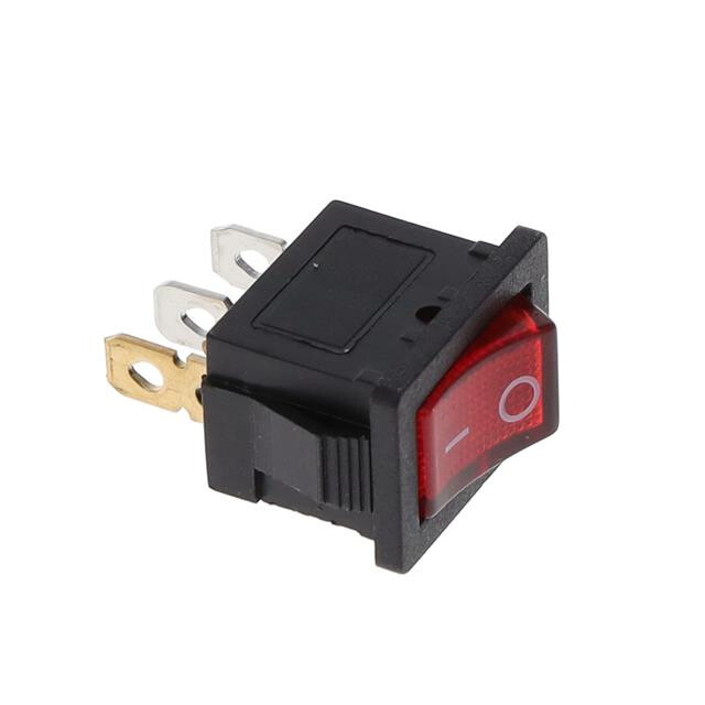
2057-SW-R2-1A-F-LR13-2-ND
Wire Ferrule

277-2205-ND
2 Conductor Wire 22 AWG

CN190BR-500-ND
0.187 Inch Quick Connect
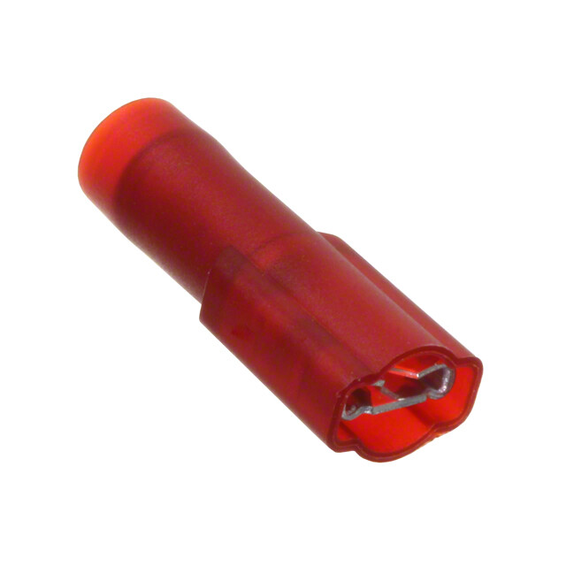
3M156217-ND
Below is the construction of the LED lighting.
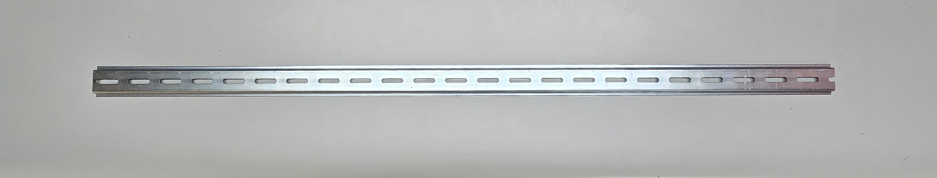
First place the DIN rail facing down

Next place the LED strip power adapter at one end of the DIN rail with the adhesive backing removed. And open the connector latch.

Insert the power contact pads into the connector and latch the connector.

Next measure out a length of the LED strip to fit the DIN rail, leaving enough for the other power adapter, if a second adapter is used.

The LED strip should be cut between the contact pads, avoid cutting through the soldered pads.

Then insert the LED power pads into the power adapter, remove the backing from the adapter and then adhere it to the DIN rail while pulling the LED strip. This will help keep the LED strip in line.
Once the LED length has been cut to length, remove the LED strip from the first connector and remove the adhesive carrier backing and insert the power pads into the connector. Peel the backing away from the LED strip along the length. Once the second adapter has been reached, disconnect to finish the peel and then re-insert. Go back along the LED strip and press down to secure the strip to the DIN rail.
Note: Once the adapters and LED strips have been installed, test them with a power supply. Check the polarity of the LED strip when wiring.

The LED lighting is mounted to the shelving using magnets, one magnet is placed on either end of the DIN rail.

The lighting is ready to be mounted to the shelving, and then be wired.
Powering the LED Strips
For this setup, each section of the 3D Printer Wall will be individually lit, except for the bottom row for the filament, three lighting sections are wired together.
The power supply used is 12V 1.5A. In testing, the LEDs draw 1.2A when two strips are wired together. The power is wired to an illuminated SPST switch and then to the LED strips.

The Adafruit power adapter 1528-1386-ND can be secured to the shelf with the 3D printed magnetic cable management mount.
The wiring of the LED strips has the power coming from the power adapter. This takes the barrel connection and converts it into the terminal block connection. Take the length needed to connect from the terminal block to the switch and crimp ferrules to the stripped leads. Using the ferrules allow for a clean install of the wires and prevents stray wires.
Next take the measured length from the LEDs to the switch location and crimp ferrules onto the wire that will connect to the LEDs. On the other end of the wires at the switch, crimp the quick connects on to each red wire. With the black wires, twist the stripped wires together, insert them into the quick connect and then crimp the wires.
Wiring the Switch


The switch plate mount was created to fit the switch and is attached to the shelf with magnets.
Magnetic Switch Plate.stl (12.2 KB)
With the switch orientated as above, connect one red wire to the middle and the other to the bottom. The joined black wires are to be connected to the top connection (brass terminal). When the switch is switched to the on position, it will be illuminated. If a non-illuminated switch is used, cut a break in the red wire and tie in the switch.


If more than one LED strips is mounted under the shelf, be sure to connect them together.
Completed DigiKey 3D Printer Wall
The DigiKey 3D Printer Wall is now setup and showcases the 3D printers in use, along with a few Labsland products. As new printers are added for use, they will be showcased on the wall.