We use cookies to provide our visitors with an optimal site experience. View our privacy notice and cookie notice to learn more about how we use cookies and how to manage your settings. By proceeding on our website you consent to the use of cookies.
I have a 12V 0.12A electromagnet and a 3-18V 1.5A ZXBM5210-SP-13 motor driver. They worked well for about a hundred fwd-rev-off cycles, but after a while one direction stopped working, then shortly after the other direction failed as well. Figured it was a fluke, but the next day another identical and independent setup failed in the same way.
The system was used as follows:
Resting state was FWD and REV both low, aka standby mode. This was for an indefinite time, anywhere from 30 seconds to days
FWD high and REV low, aka forward mode. This was for 6-30 seconds.
FWD low and REV high, aka reverse mode. This was for 0.25 seconds, to degauss the magnet.
Back to state 1
The driver has a built in ‘dead-time’ between direction reversals, so I doubt the instant switch from forward to reverse caused the issue since the hardware protects from such problems.
I disconnected the magnet to eliminate faulty magnet as a source of the error, then with my scope I’ve confirmed these pin states:
2v nominal, with a 11.8v 10μs pulse every 4.74ms (picture of pulse included)
12v
12v
5v
0v
12v
2.2v
0v
I’m at a loss for what’s happening, the magnets measure 100 ohms (both unused and the used), so I’d expect the inrush to only be .12A at startup, far below what the driver is rated for. The driver’s made for dc motors so I would expect it to handle inductive loads easily.
Here is some suggestions that I received As I am not sure what is going on for sure, but with 12V and 100Ω, he should have a .12A once its been powered for a bit, but if that electromagnet functions at all like a motor, you can expect a much larger inrush current. I’ve seen pump motors draw 5x their running current upon start when under load.
Placing a current sense resistor (very low Ω) and reading across that with the scope while powering and especially during a reversal, would be valuable to help rule out the inrush and to see what possible spikes may be occurring upon removing power. (although that seems unlikely as you have to really have a fast ‘turn-off’ time to get a highly inductive spike)
That’s a good idea, I think you may be onto something with the kickback during a reversal. I was under the impression the inrush upon start was due to the low resistance of the motor coils?
That was my understanding with transformers, roughly 1.8ohms until the core is saturated then the effective resistance goes to much more manageable levels. In the case of the magnet it’s at 100ohms unsaturated so I’d expect there to be minimal inrush.
During reversal I’m not sure though, there’s the opposite inrush but also the collapse of the magnetic field, I’m uncertain how those two interact together. I’ll do some tests and report back with what I find.
To see 2.2v at an output (pin 7) that’s supposed to be near zero would suggest damage to the low-side transistor on that half of the bridge.
An electromagnet such as this is likely to be significantly more inductive than a motor of similar input ratings; voltage stresses, rather than current, seem likely to be the problem. The suggested use of C2 (datasheet page 2) is a good idea; larger values than suggested may be called for.
I have a 2200μF electrolytic standing in for c2, but it’s 60mm away due to layout constraints. Far from ideal but I wasn’t anticipating this issue. Is it possible the capacitor can’t react fast enough like a ceramic can?
I’m thinking two 14v zener diodes in antiseries between the magnet’s terminals may be the easiest fix without getting new PCBs made. The thought is any voltage spike will get snubbed before it gets to the IC.
Clamping the load wouldn’t hurt; a bi-directional TVS diode might be more convenient than a pair of zeners.
Sadness due to inductive switching tends to happen on time scales similar to the switching event itself. Looking at the transitions more closely may prove instructive.
TVS diode looks perfect, seems like there’s always a new component to learn about haha.
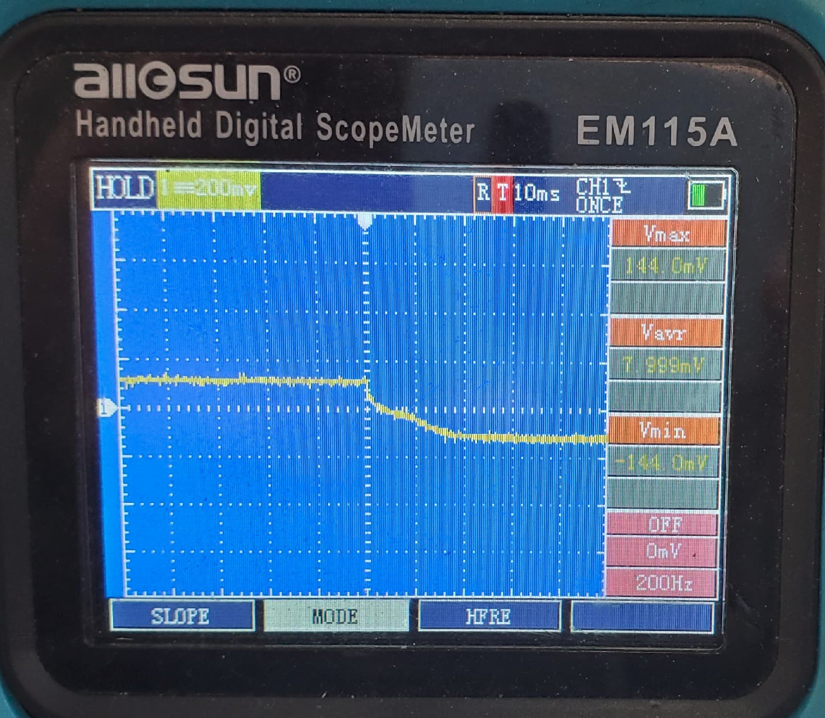
I put my 10x probe on the electromagnet leads and ended up with the plot below. Voltage is staying in range the whole time, not sure if it’s due to the internal diodes in the motor driver clamping the voltage though. That, or my setup isn’t fast enough to capture any spike that is happening. Measured a 1ohm resistor in series with the magnet during the reversal, nothing interesting there either, max current is 0.14A +/- 5%. But again, my setup may be too slow to see the interesting parts. I adjusted the timescale but even at 500us there wasn’t anything but noise to see.
I did omit C1 and C2 from the Typical Applications Circuit on page 2, I’m going to add a 0.22μF and 1μF and cross my fingers that keeps the driver from failing. None of these measurements so far have revealed a smoking gun so I don’t have a lot of confidence, but it’s worth a shot. I’ll order some TVS diodes and some spare drivers in the meantime while we wait to see if another driver fails with the capacitors added.
Measuring across OUT1 and OUT2 during FWD to REV switch:
I posted this question on reddit shortly after posting here to get a larger audience, u/quadrapod suggested adding a 0.1μF capacitor to each of the output pins (as well as the 1μF re-circulation capacitor I omitted). I had those capacitors on hand so I soldered them on and let the system run to see if the drivers failed again. After roughly 5000 cycles there’s no indication of failure and all seems to be working well.
I’m still waiting for the TVS diodes to arrive in the mail, those will probably get added as well as a second layer of protection, but it seems the problem has been solved. Thank you both for your help!