Signal Ground
The ground you may most be familiar with in an electronic circuit is signal ground (also called digital ground, analog ground, and often referred to as “ground” with no context). When you work with pure DC from a source not connected to earth ground, (such as a battery, external DC source isolated from Earth, adapters with no third AC prong), this is usually referred to as a “floating ground”. This simply means it is an isolated reference point for circuits not connected to earth ground. What do engineers mean by a reference point though? It took me a while to figure this out on my own. I like to think of it as the 0-volt reference point of the circuit. Voltage is always a “differential” when it comes to measurement, volt meters always measure from one point compared to another. In many cases, you measure in reference to the signal ground; the 0-volt common return for all components. Remember Kirchoff’s voltage law that the sum of all voltage potentials in a circuit or complete loop must equal zero. If you use the positive lead on a multimeter where you have all wires tied back to the negative terminal of the voltage source and measure across a component, you’ll see a negative voltage readout. The value should be the same if you switch the leads around and be the same value but positive. This helps give context to the idea of a “0-volt” reference point. Here are some symbols you may see in diagrams:


Note: some circuit diagrams have these symbols at the other side of components with no other wires present, see the diagram below.

To save room on diagrams, these “detached ground symbols” are placed. In reality, there is technically a “invisible wire” connecting these points together. This image may help visualization:
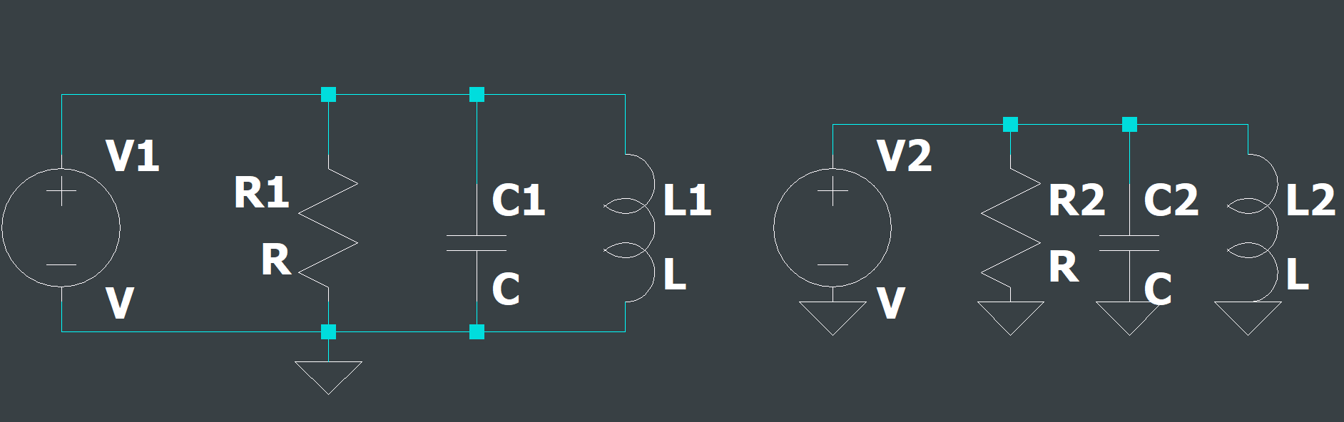
The left circuit is the same as the right.
With low voltage sources, you rarely see any application tied to earth ground. If you use a supply that does have a third prong, there is a possibility that the DC signal ground is connected to the AC ground (green wire) for regulation purposes. Some AC/DC converters do not tie grounds together if it is not required, floating ground points are often intentional as tying some grounds together creates ground loops. These often cause massive amounts of noise generation in one or both circuits.
Chassis Ground
The final type of ground seen in diagrams is called Chassis Ground. Chassis ground is almost always tied to earth ground in some way and is often used for EMI suppression and protection against transient spikes. This is not to be confused with automotive standards where the chassis is typically a return path for the negative terminal of the battery. There are many connections in vehicles, so it is far more efficient to use the chassis and/or engine as the return when components can be placed far from the battery. Here is a symbol for chassis ground:
