We use cookies to provide our visitors with an optimal site experience. View our privacy notice and cookie notice to learn more about how we use cookies and how to manage your settings. By proceeding on our website you consent to the use of cookies.
We even changed the microcontroller that we are using from 10bit to 14bit and even tested it to external 16bit.
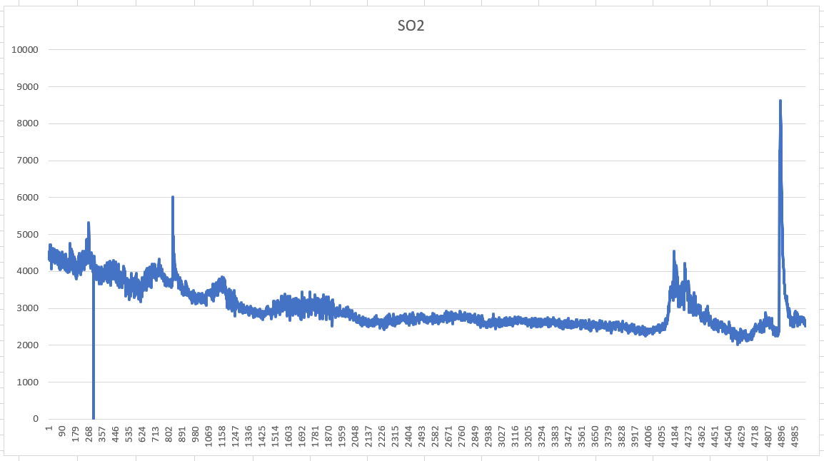
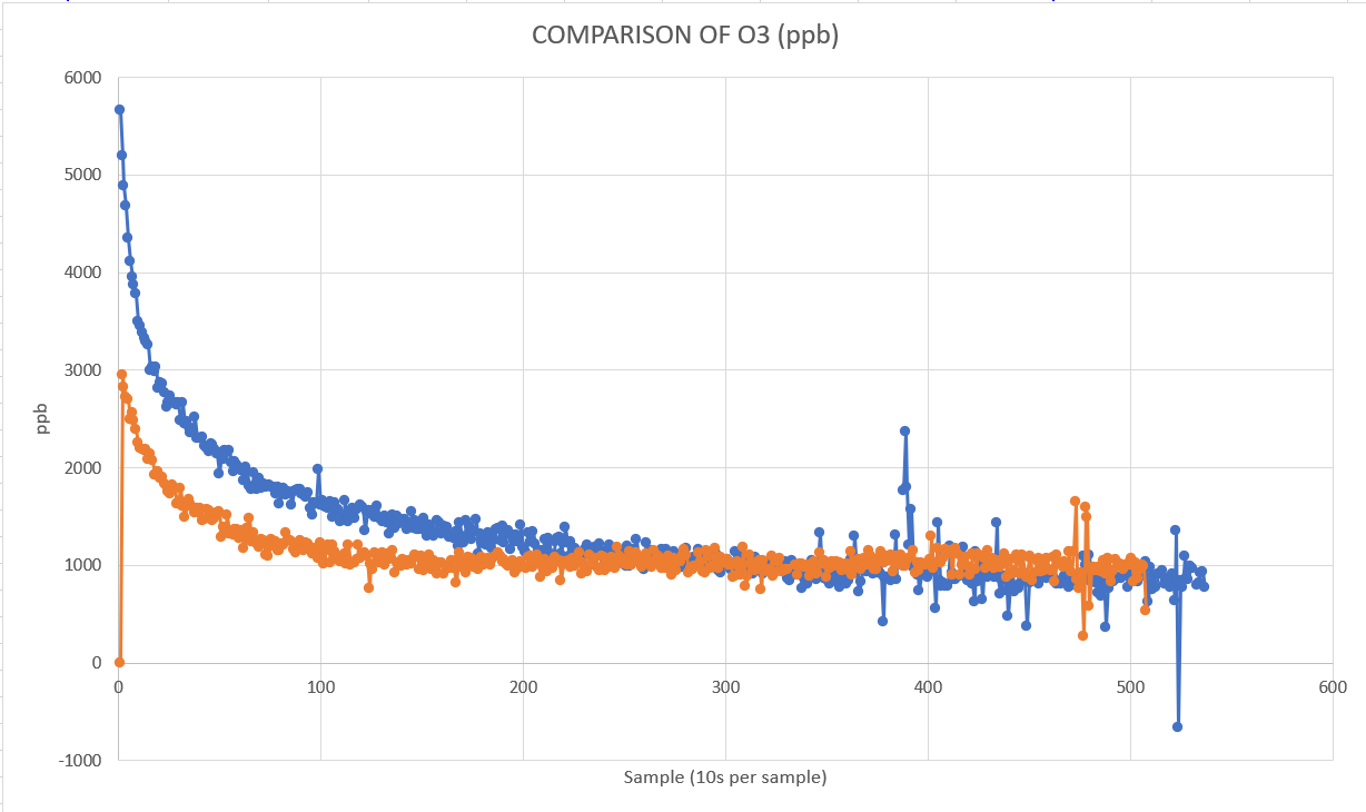
However, the results of these 2 sensors were always around 1000ppb ozone and NO2 (even after stabilization). The SO2 on the other hand ranges from 2k-3k ppb
Attached below are the readings that we measured
As you can see we were not able to reach the standard limit and measure below our range of interest (0-100ppb)
The README in the referenced software repo recommends use of the evaluation board that comes with the sensors packaged as SDKs, and the software in that repo appears to have been written with this use in mind. Skipping down to the “use 2x 10K resistors” part of the README without making adjustments to the software to accommodate this change in the system is likely to cause unexpected results.
This portion of the schematic shows that the Vref potential, as produced by the ULPSM board, is created using a high-impedance voltage divider that is also used to create a bias voltage for the sensor, as described in the Operation Overview. The software is set up with the understanding that the potentials being measured were created by this arrangement.
By overdriving the Vref pin using an external, lower-impedance voltage divider, one disrupts how the Vref and sensor bias potentials are controlled, making the calculations done by the software invalid. This is perhaps also a response to the related post from the standpoint the ULPSM’s Vref pin is neither an input or an output; it is a high-impedance analog node. It will take on a (more or less) defined potential if measured carefully, but will easily take on other potentials depending on what’s connected.
Buffering and measuring the Vref pins for each sensor as suggested in the README should permit the provided example code to work more or less as intended. (Either the SPEC evaluation boards or a suitable analog circuit will do.) Otherwise, the sample code will need to be modified to account for changes to the analog system in order to provide reasonable results.
Upon checking the schematic the schematic shown there is not updated it is 1.1 where as we are using ULPSM rev 1.2 (see attached) may we request an updated copy of the ULPSM Schematic.
I also reviewed the code of David Peasle and the initialization such as the gain, bias are correct for each sensor. As programmed in the ULP library (See attached code initialization 1 and the numbers indicated in the ULPSM board). Not to mention that the way the code works always ask for the removal of the sensor to get the Voltage Reference that will be used in the code as a reference (see initialization 2 ) that is why when the expected value (the expected value is around Vcc/2) is not met there is a recheck of settings and are promp to fix the connection in order to run the program properly. That is why I think there is no problem in the code (since we also have a CO spec sensor and it works fine)
Regarding the development board there are 2 practical reasons why we did not consider the evaluation board.
(1) It is expensive considering that we need at least 3.
(2) The overall system is attached on the drone thus, considering that we need 3 evaluation board the weight would increase thus affecting the flight performance of the quadcopter.
On closer inspection, the external reference divider may not have as much influence as I’d thought at first; its use will change the bias applied to the sensor somewhat, but that may not the answer here–my error…
Backing up a bit, I’d ask about your setup and calibration procedures for these sensors–put differently, what was the procedure used to obtain the charted data?
We used adafruit itsybitsy nrf52840 due to its form factor and analog capability of up to 14 bits. However, we decided to use adafruit ADS1115 breakout board to serve as an external ADC for the reason that it gives us more resolution. And we found out that may it be 10, 12, 14 or 16 bit the average result of the reading would be the same 1k ppb for ozone.
The power supply of the sensor came from Adafruit itsybitsy nrf52840, and a voltage divider 2x10k ohm as recommended.
We used the ULPSM library for calculation and the default example. We just modified it accordingly such as the calibration factor that can be seen at the back of the sensor, Measured Vsupply, and the voltage reference of the microcontroller.
The program prompts us to remove the sensor to calculate the Vref. It would be the baseline of the calculation.
Afterwhich we waited for more than an hour some experiments waited for more than 8 hours but the results are almost the same.
In asking about the setup and calibration procedures used, I was asking more about the process used for calibration of the zero-concentration output value. The ULPSMs and the sensors themselves have offsets which need to be accounted for before measurements in the range of the EPA limits can be made. This would involve allowing the sensors to stabilize under bias in an environment known to be free of the target gas and any cross-sensitive gasses, and calling the zero() function in the example code. It’s possible that some error could be introduced by these procedures through humidity, pressure, or adsorption effects. AN-104, -105, and -106 would be worth reading.
Using higher-resolution ADCs would likely be helpful in some ways, but it seems unlikely to have much effect on offset problems. As delivered, the gains of the ULPSMs are low enough that only a small portion of the analog output range is used. The entire 0~20PPM range of the SO2 sensor for example, produces an analog output change of only 60 mV if I’ve read correctly. This may account for what looks like a large amount of noise in the data shown from that sensor.
I would also offer the observation that since the impedance of these circuits is quite high, it is very possible that one could encounter problems related to static charge accumulation or leakage across the surface of the PCB.