Code Downloads
Joystick Pmod Controller (top-level file): pmod_joystick.vhd (10.1 KB)
SPI Master (must also be included in the project): spi_master.vhd (8.9 KB)
Features
- VHDL source code of a streamlined interface to Digilent’s Pmod JSTK2
- Continually outputs the latest x-axis and y-axis position data on parallel buses
- Continually outputs the latest status of the trigger and center buttons
- Handles SPI communication to retrieve data from the Joystick Pmod
- Configurable system clock rate
Introduction
This details a VHDL component that handles interfacing to Digilent’s Joystick JSTK2 Pmod, shown in Figure 1. Figure 2 illustrates a typical example of this Joystick Pmod Controller integrated into a system. As shown, the Joystick Pmod Controller connects to the Pmod ports and executes transactions to gather data. The data is continually updated and presented on 2 simple parallel buses (corresponding to the 2 axes) and 2 single bit outputs (corresponding to the buttons), which can be connected to user logic or to output ports on the FPGA.

Figure 1. Digilent Joystick JSTK2 Pmod
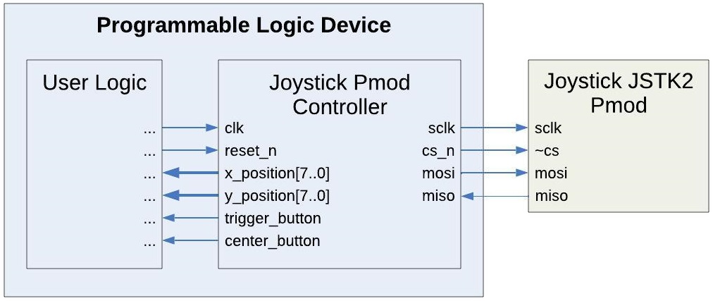
Figure 2. Example Implementation
Theory of Operation
The Joystick Pmod Controller consists primarily of a state machine and an SPI Master component. It requests a 7-byte packet from the Pmod and parses this to retrieve the position data and buttons’ status.
State Machine
The design uses the state machine depicted in Figure 3 to implement its operation. Upon start-up the component immediately enters the start state. It remains in this state for 100ms to ensure the Pmod has ample time to power-up. It then proceeds to the initiate_transaction state. Here, it sets the Pmod’s chip select signal and waits 15us before advancing to the byte_transact state. This state uses the SPI Master component to conduct an 8-bit SPI communication with the joystick. The subsequent byte_pause state keeps track of the number of bytes sent and performs a 10us pause between bytes. Once all bytes in the packet complete, it continues to the output_results state. The results are presented on the x_position, y_position, trigger_button, and center_button output ports, and the design waits for 1ms before returning to the initiate_transaction state to begin the process of acquiring the next data set. Although not shown, resetting the component at any time returns it to the start state.

Figure 3. State Diagram
SPI Master
During the byte_transact state, the state machine controls an SPI Master component to communicate with the microcontroller on the Pmod. Documentation for the SPI Master is available here.
This design implements the SPI master in the CPOL = ‘0’ and CPHA = ‘0’ mode. It sets the clk_div parameter based on the system clock frequency (specified with the clk_freq generic parameter, see below) to communicate with the Pmod at the 1MHz bus speed specified in the Pmod’s reference manual.
This design does not use the SPI Master’s slave select. The Pmod has some unorthodox timing requirements, including a 15us pause between the chip select and the first byte and also 10us pauses between bytes. Due to this, the design uses a separate chip select, and the SPI Master conducts a separate transaction for each byte within the data packet.
System Clock Frequency
The generic parameter clk_freq must be set to the frequency of the system clock provided to the Joystick Pmod Controller on its clk port.
Port Descriptions
Table 1 describes the Joystick Pmod Controller’s ports.
Table 1. Port Descriptions

Connections
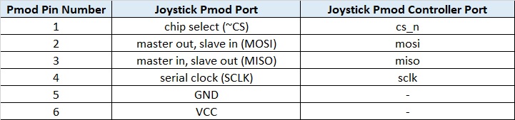
This Pmod has a 6-pin connector. Table 2 provides the pinout for this connector. The Joystick Pmod Controller’s ports need to be assigned to the FPGA pins that are routed to this connector as listed.
Table 2. Joystick Pmod Pinout and Connections to Joystick Pmod Controller
Reset
The reset_n input port must have a logic high for the Joystick Pmod Controller component to operate. A low logic level on this port asynchronously resets the component. During reset, the component aborts the current transaction with the Pmod and clears the x_position, y_position, trigger_button, and center_button data outputs. Once released from reset, the Joystick Pmod Controller restarts its operation and resumes collecting and outputting joystick data.
Conclusion
This Joystick Pmod Controller is a programmable logic component that interfaces to Digilent’s Pmod JSTK2. It handles all communication with this Pmod to provide a continual stream of updated position and button data.