Code Downloads
Gyro L3G4200D Pmod Controller (top-level file):
Verison 1.1: pmod_gyro_l3g4200d.vhd (12.2 KB)
Fixed potential intermittent problem coming out of reset
Version 1.0: pmod_gyro_l3g4200d_v1_0.vhd (12.0 KB)
Initial Public Release
SPI Master (must also be included in the project):
spi_master.vhd (8.9 KB)
Features
- VHDL source code of a streamlined interface to Digilent’s Pmod GYRO (Pmod for ST Microelectronics L3G4200D Gyro)
- Continually outputs latest 3-axis gryo data on 3 parallel buses
- Handles SPI communication to configure and retrieve data from the Gyro Pmod
- Configurable gryo data range
- Configurable gryo bandwidth
- Configurable system clock rate
Introduction
This details a VHDL component that handles interfacing to Digilent’s Gyro L3G4200D Pmod, shown in Figure 1. Figure 2 illustrates a typical example of this Gyro Pmod Controller integrated into a system. As shown, the Gyro Pmod Controller connects to the Pmod ports and executes transactions to configure the gryo and gather data. The data is continually updated and presented on 3 simple parallel buses (corresponding to the 3 axes), which can be connected to user logic or to output ports on the FPGA. The data is presented in 2’s complement.

Figure 1. Digilent Gyro L3G4200D Pmod

Figure 2. Example Implementation
Theory of Operation
The Gryo Pmod Controller consists primarily of a state machine and an SPI Master component.
State Machine
The design uses the state machine depicted in Figure 3 to implement its operation. Upon start-up the component immediately enters the start state. It remains in this state for 100ms to ensure the Pmod has ample time to power-up. It then proceeds to the configure state, where it writes to a control register on the gyro to set the data rate and bandwidth and to bring the gyro out of its default power-down mode into normal mode. The pause state inserts a 1ms period between SPI transactions (i.e. between gyro readings). In the read_data state, it gathers the most recent angular rate data for all 3 axes from the gyro, then continues to the output_result state. The output_result state writes the data to the angular_rate_x, angular_rate_y, and angular_rate_z output buses, then returns to the pause state. Resetting the component at any time returns it to the start state.

Figure 3. State Diagram
SPI Master
During the configure and read_data states, the state machine controls an SPI Master component to communicate with the gyro on the Pmod. Documentation for the SPI Master is available here.
This design implements the SPI master in the CPOL = ‘1’ and CPHA = ‘1’ mode. It sets the clk_div parameter based on the system clock frequency (specified with the clk_freq generic parameter, see below) to communicate with the gyro at or close to 5 MHz.
This design also utilizes the Continuous Mode feature of the SPI Master to execute transactions of varying lengths. The transactions in the configure state are 16 bits long, whereas the transactions in the read_data state are comprised of 56 bits.
Configuring the Gryo Pmod Controller
The Gyro Pmod Controller is configured by setting the generic parameters in the entity.
System Clock Frequency
The generic parameter clk_freq must be set to the frequency of the system clock provided to the Gyro Pmod Controller on its clk port.
Data Rate and Bandwidth
The generic parameter data_rate defines the frequency at which the L3G4200D gyro takes measurements. The parameter itself is a code that corresponds to the desired data rate. Likewise, the generic parameter bandwidth is a code that corresponds to the desired bandwidth. Bandwidth depends on data rate. Table 1 below lists the available options.
Table 1. Data Rate and Bandwidth Options

Port Descriptions
Table 2 describes the Gyro Pmod Controller’s ports.
Table 2. Port Descriptions

Connections
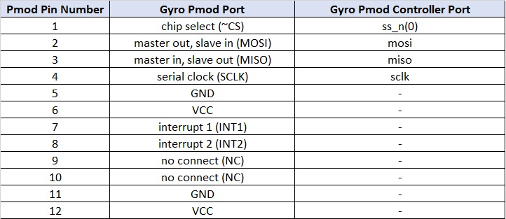
This Pmod has a 12-pin right-angle connector J1 when using SPI for communication. Table 3 provides the pinout for this connector. The Gyro Pmod Controller’s ports need to be assigned to the FPGA pins that are routed to this connector as listed.
Table 3. Gyro Pmod J1 Pinout and Connections to Gyro Pmod Controller
Reset
The reset_n input port must have a logic high for the Gyro Pmod Controller component to operate. A low logic level on this port asynchronously resets the component. During reset, the component aborts the current transaction with the Pmod and clears the angular_rate_x, angular_rate_y, and angular_rate_z data outputs. Once released from reset, the Gyro Pmod Controller restarts its operation. It reconfigures the gyro and then resumes collecting and outputting angular rate data.
Conclusion
This Gyro Pmod Controller is a programmable logic component that interfaces to Digilent’s Pmod GYRO (Gyro L3G4200D Pmod). It handles all communication with this Pmod to configure the Pmod gyro’s data rate and bandwidth, activate measurements, and provide a continual stream of updated angular rate data on 3 parallel output buses, one for each axis.