Code Downloads
Compass Pmod Controller (top level file): pmod_compass.vhd (13.7 KB)
I2C Master (must be included in project): i2c_master.vhd (14.1 KB)
Features
- VHDL source code of a streamlined interface to Digilent’s Pmod CMPS2 (Pmod for Memsic’s MMC34160PJ magnetometer)
- Continually outputs latest magnetic field data on 3 parallel interfaces (one per axis)
- Handles I2C communication and all data retrieval from the Compass Pmod
- Handles configuration of the magnetic sensor’s resolution and measurement frequency
- User selectable resolution and measurement frequency
- Configurable system clock rate
Introduction
This details a VHDL component that handles interfacing an FPGA to Digilent’s 3-axis Digital Compass Pmod, shown in Figure 1. Figure 2 illustrates a typical example of this Compass Pmod Controller integrated into a system. As shown, the Compass Pmod Controller connects to the Pmod ports and executes transactions to configure the Pmod and gather data. The data is continually updated and presented on 3 simple parallel interfaces, corresponding to the x-axis, y-axis, and z-axis magnetic field data values.

Figure 1. Digilent 3-axis Digital Compass Pmod

Figure 2. Example Implementation
Theory of Operation
The Compass Pmod Controller consists primarily of a state machine and an I2C Master component.
State Machine
The design uses the state machine depicted in Figure 3 to implement its operation. Upon start-up the component immediately enters the start state. It remains in this state for 10ms to ensure the Pmod has ample time to power-up. It then proceeds to the configure state, where it sets the resolution of magnetometer’s outputs, puts the magnetometer into Continuous Measurement Mode, and sets the frequency of these continuous measurements. The pause state implements a pause equal to the period of the measurement frequency. In the following read_data state, the controller gathers the most recent magnetic field data from the Pmod. Finally, it outputs the data in the output_result state. It then continuously cycles between the pause, read_data, and output_result states to keep the magnetic field data updated. Although not shown in the state diagram, resetting the component at any time returns it to the start state.
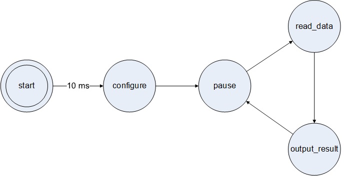
Figure 3. State Diagram
I2C Master
During the configure and read_data states, the state machine controls an I2C Master component to communicate with the MMC34160PJ magnetometer on the Pmod. Documentation for the I2C Master is available here.
Configuring the Compass Pmod Controller
The Compass Pmod Controller is configured by setting the generic parameters in the entity.
System Clock Frequency
The generic parameter sys_clk_freq must be set to the frequency of the system clock provided to the Compass Pmod Controller on its clk port.
Resolution
The generic parameter resolution sets the resolution of the magnetic field measurements. This parameter also sets the width of the x, y, and z data outputs. Valid options are 12, 14, and 16 bits. The default is 16 bits. Setting resolution to any invalid value also results in a resolution of 16 bits.
Update Frequency
The generic parameter update_freq sets the measurement frequency and frequency at which the x, y, and z data outputs update. The parameter values correspond to the bits required by the magnetometer’s control register to set the measurement frequency. Table 1 lists the valid parameter settings and resulting update frequency. The default setting is “11” (50 Hz).
Table 1. Update Frequency Settings

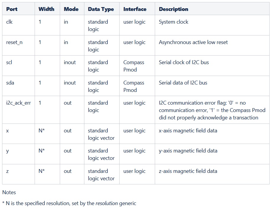
Port Descriptions
Table 2 describes the Compass Pmod Controller’s ports.
Table 2. Port Descriptions
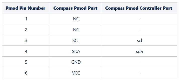
Connections
This Pmod has a 6-pin connector. Table 3 provides the pinout for this connector. The Compass Pmod Controller’s ports need to be assigned to the FPGA pins that are routed to this connector as listed.
Table 3. Compass Pmod Pinout and Connections to Compass Pmod Controller
The Pmod also has two jumpers. These must be enabled (i.e. connected) to connect the required I2C pull-up resisters for SCL and SDA.
Reset
The reset_n input port must have a logic high for the Compass Pmod Controller component to operate. A low logic level on this port asynchronously resets the component. During reset, the component aborts the current transaction with the Pmod and clears the x, y, and z data outputs and the i2c_ack_err output. Once released from reset, the Compass Pmod Controller restarts its operation. It reconfigures the Pmod and resumes collecting and outputting magnetic field data.
Conclusion
This Compass Pmod Controller is a programmable logic component that interfaces to Digilent’s Pmod CMPS2 (3-axis Digital Compass Pmod). It handles all communication with this Pmod to configure the Pmod’s magnetometer and provide a continual stream of updated magnetic field data on parallel outputs.