Code Downloads
ADC AD7991 Pmod Controller (top level file): pmod_adc_ad7991.vhd (12.5 KB)
I2C Master (must also be included in the project): i2c_master.vhd (14.1 KB)
Features
- VHDL source code of a streamlined interface to Digilent’s PmodAD2 (Pmod for Analog Device’s AD7991 Analog-to-Digital Converter)
- Continually outputs latest data for each of the 4 converter channels on 4 corresponding parallel interfaces
- Handles I2C communication and all data retrieval from the ADC Pmod
- Configurable system clock rate
Introduction
This details a VHDL component that handles interfacing to Digilent’s ADC AD7991 Pmod, shown in Figure 1. Figure 2 illustrates a typical example of this ADC Pmod Controller integrated into a system. As shown, the ADC Pmod Controller connects to the Pmod’s I2C ports and executes transactions to gather data from each of the ADC’s 4 converter channels. The data is continually updated and presented on simple parallel interfaces which can be connected to user logic or to output ports on the FPGA.

Figure 1. Digilent ADC AD7991 Pmod
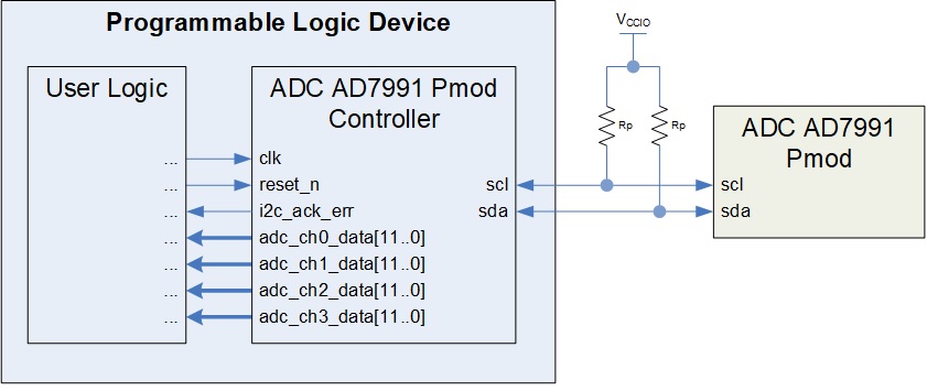
Figure 2. Example Implementation
Theory of Operation
The ADC Pmod Controller consists primarily of a state machine and an I2C Master component.
State Machine
The design uses the state machine depicted in Figure 3 to implement its operation. Upon start-up, the component immediately enters the start state. It remains in this state for 100ms to ensure the Pmod has ample time to power-up. In the following read_data state, it gathers the most recent ADC data from the Pmod’s ADC. It completes this data transfer in a single I2C transaction and stores both the 4-bit header and 12-bit data from each ADC channel in a separate data buffer. In the output_result state, it uses the header information to route each of the 12-bit data results to the correct parallel output. It then continuously cycles between the read_data and output_result states to keep the ADC data constantly updated. Resetting the component at any time returns it to the start state.

Figure 3. State Diagram
I2C Master
During the read_data state, the state machine controls an I2C Master component to communicate with the ADC on the Pmod. Documentation for the I2C Master is available here .
System Clock Frequency
In the entity, the generic parameter sys_clk_freq must be set to the frequency (in Hz) of the system clock provided to the ADC Pmod Controller on its clk port.
I2C Pull-Up Resistors
Unlike most of Digilent’s Pmod boards, the I2C pull-up resistors shown in Figure 2 above are not included on the PmodAD2. The I2C bus will not operate correctly without them.
The user can solve this problem by wiring 2.2 kΩ resistors into the circuit as shown.
Several of Digilent’s other Pmods use I2C, include these resistors, and also include connectors to plug additional Pmods into the same I2C bus. If this ADC Pmod is used in conjunction with one those Pmods, the user can automatically take advantage of the pull-up resistors already included on those boards and no further action is needed.
I2C Address
Digilent’s reference manual for the PmodAD2 states to use “0101000” for the I2C address when communicating with the AD7991. However, Analog Devices produces multiple versions of the AD7991 with different I2C addresses (see Table 8 on page 12 of the datasheet). Part number AD7991-0 uses address “0101000”, while part number AD7991-1 uses address “0101001”.
Unfortunately, Digilent has produced this Pmod using both versions (probably inadvertently), so some Pmods will not work as described. The version on a particular Pmod can be determined by looking at the part marking on the AD7991, as shown in Figure 4.

Figure 4. AD7991 Part Markings
“C55” indicates the AD7991-0 part, so no changes are needed.
“C56” indicates the AD7991-1 part, so line 119 of the pmod_adc_ad7991.vhd file must be changed to reflect this discrepancy:
i2c_addr <= "0101001";
Port Descriptions
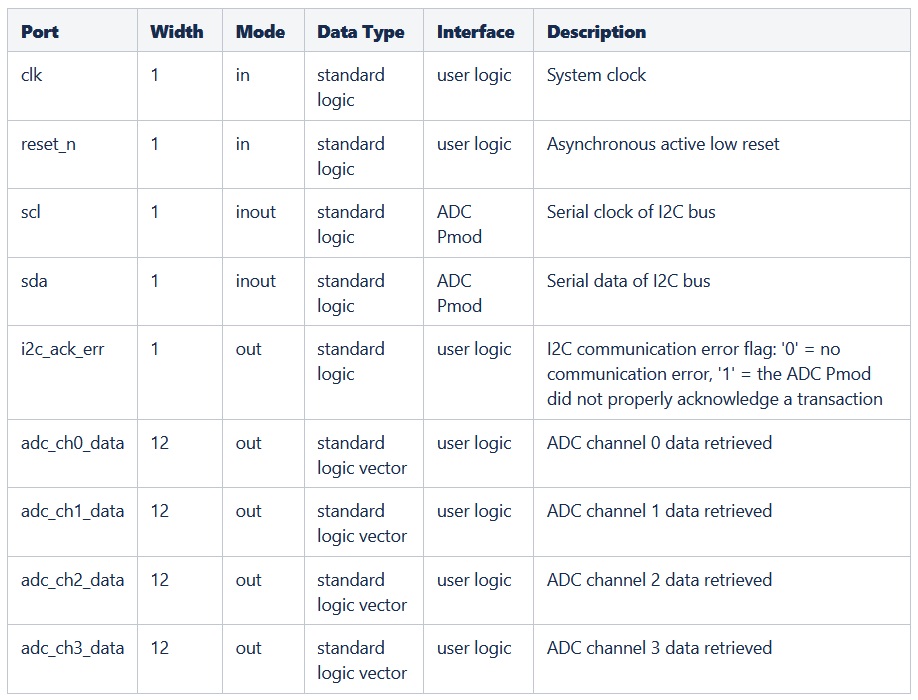
Table 1 describes the ADC Pmod Controller’s ports.
Table 1. Port Descriptions
Connections
This Pmod has an 8-pin connector. Table 2 provides the pinout for this connector. The ADC Pmod Controller’s ports need to be assigned to the FPGA pins that are routed to this connector as listed. The two rows of the J1 connector are tied together on the Pmod board, so only one side needs to be connected to the FPGA.
Table 2. ADC 7991 Pmod Pinout and Connections to ADC Pmod Controller

The Pmod also has a jumper. JP1 must connect the middle pin to the pin labeled V4. This connects the 4th channel on the ADC to its input pin on the J2 connector, thus enabling its use.
Reset
The reset_n input port must have a logic high for the ADC Pmod Controller component to operate. A low logic level on this port asynchronously resets the component. During reset, the component aborts the current transaction with the Pmod. It clears the parallel data outputs and the i2c_ack_err output. Once released from reset, the ADC Pmod Controller restarts its operation and resumes collecting and outputting ADC data.
Conclusion
This ADC AD7991 Pmod Controller is a programmable logic component that interfaces to Digilent’s PmodAD2 (ADC AD7991 Pmod). It handles all communication with this Pmod to gather data from the Pmod ADC’s 4 channels and provide a continual stream of updated data on 4 corresponding parallel outputs.