Code Downloads
NAV Pmod Controller (top level file): pmod_nav.vhd (30.9 KB)
SPI Master (must also be included in project): spi_master.vhd (8.9 KB)
Features
- VHDL source code of a streamlined interface to Digilent’s Pmod NAV (Pmod for ST Microelectronics LSM9DS1 iNEMO inertial module and LPS25HB pressure sensor)
- Continually outputs latest 3-axis accelerometer data on 3 parallel buses
- Continually outputs latest 3-axis gryo data on 3 parallel buses
- Continually outputs latest 3-axis magnetometer data on 3 parallel buses
- Continually outputs latest pressure data on a parallel bus
- Handles SPI communication to configure and retrieve data from the NAV Pmod
- Configurable accelerometer output data rate and full scale range
- Configurable gryo output data rate and full scale range
- Configurable magnetometer output data rate and full scale range
- Configurable pressure sensor data rate
- Configurable system clock rate
Introduction
This details a VHDL component that handles interfacing to Digilent’s 10-DOF NAV Pmod, shown in Figure 1. Figure 2 illustrates a typical example of this NAV Pmod Controller integrated into a system. As shown, the NAV Pmod Controller connects to the Pmod ports and executes transactions to configure the accelerometer, gryo, magnetometer, and pressure sensor. It then continuously gathers data. The data is updated and presented on simple parallel buses (one for each degree of freedom), which can be connected to user logic or to output ports on the FPGA.

Figure 1. Digilent NAV Pmod

Figure 2. Example Implementation
Theory of Operation
The NAV Pmod Controller consists primarily of a state machine and an SPI Master component.
State Machine
The design uses the state machine depicted in Figure 3 to implement its operation. Upon start-up the component immediately enters the start state. It remains in this state for 200ms to ensure the Pmod has ample time to power-up.
It then proceeds through a series of configuration states, where it writes to various control registers on the iNEMO inertial module and the MEMS pressure sensor to configure their respective sensors and start their operation. The configure_accelerometer state sets the accelerometer’s full scale range. The configure_magnetometer state puts the magnetometer into high performance mode for all axes, into continuous conversion mode, and sets its output data rate and full scale range. The configure_gyro state configures both the accelerometer’s and gyro’s output data rates (they must be the same) and also sets the gyro’s full scale range. The configure_pressure state puts the pressure sensor into active mode and configures its output data rate.
Once configuration is complete, the pause state inserts a 1ms period between data readings, as the maximum data rate for any sensor is less than 1kHz. The state machine proceeds through the read_data_accelerometer, read_data_magnetometer, read_data_gyro, and read_data_pressure states, collecting data from each sensor. Finally, it outputs the resulting data on the parallel output buses during the output_result state before pausing again until the next data collection.
Although not shown, resetting the component at any time returns it to the start state.
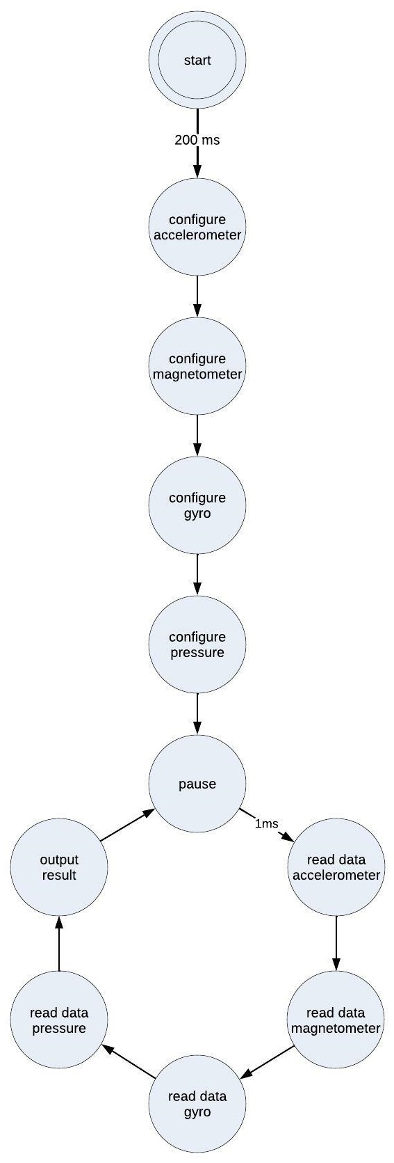
Figure 3. State Diagram
SPI Master
During the various configure and read_data states, the state machine controls an SPI Master component to communicate with the sensors on the Pmod. Documentation for the SPI Master is available here.
This design implements the SPI master in the CPOL = ‘1’ and CPHA = ‘1’ mode. It sets the clk_div parameter based on the system clock frequency (specified with the clk_freq generic parameter, see below) to communicate with the sensors at or close to 5 MHz.
This design also utilizes the Continuous Mode feature of the SPI Master to execute transactions of varying lengths.
Configuring the NAV Pmod Controller
The NAV Pmod Controller is configured by setting the generic parameters in the entity.
System Clock Frequency
The generic parameter clk_freq must be set to the frequency (in MHz) of the system clock provided to the NAV Pmod Controller on its clk port.
Accelerometer and Gyro Data Rate
The generic parameter accelerometer_gyro_data_rate defines the frequency at which the accelerometer and gyro take measurements. There is only a single parameter, since the two must have the same data rate. The parameter itself is a code that corresponds to the desired data rate. Table 1 below lists the available options. The default is “110”, i.e. 952Hz.
Table 1. Accelerometer and Gyro Data Rate Options

Accelerometer Full Scale
The generic parameter accelerometer_full_scale defines the accelerometer’s data range. The parameter itself is a code that corresponds to the desired range. Table 2 below lists the available options. The default is “00”, i.e. ±2 g.
Table 2. Accelerometer Full Scale Options

Gyro Full Scale
The generic parameter gyro_full_scale defines the gyro’s data range. The parameter itself is a code that corresponds to the desired range. Table 3 below lists the available options. The default is “00”, i.e. 245dps.
Table 3. Gyro Full Scale Options

Magentometer Data Rate
The generic parameter magnetometer_data_rate defines the frequency at which the magnetometer takes measurements. The parameter itself is a code that corresponds to the desired data rate. Table 4 below lists the available options. The default is “111”, i.e. 80Hz.
Table 4. Magnetometer Data Rate Options

Magnetometer Full Scale
The generic parameter magnetometer_full_scale defines the magnetometer’s data range. The parameter itself is a code that corresponds to the desired range. Table 5 below lists the available options. The default is “00”, i.e. ±4 gauss.
Table 5. Magnetometer Full Scale Options

Absolute Pressure Data Rate
The generic parameter pressure_data_rate defines the frequency at which the pressure sensor takes measurements. The parameter itself is a code that corresponds to the desired data rate. Table 6 below lists the available options. The default is “100”, i.e. 25Hz.
Table 6. Pressure Sensor Data Rate Options

Port Descriptions
Table 7 describes the NAV Pmod Controller’s ports.
Table 7. Port Descriptions

Connections
This Pmod has a 12-pin right-angle connector J1. Table 8 provides the pinout for this connector. The NAV Pmod Controller’s ports need to be assigned to the FPGA pins that are routed to this connector as listed.
Table 8. NAV Pmod J1 Pinout and Connections to NAV Pmod Controller

Reset
The reset_n input port must have a logic high for the NAV Pmod Controller component to operate. A low logic level on this port asynchronously resets the component. During reset, the component aborts the current transaction with the Pmod and clears the acceleration_x, acceleration_y, acceleration_z, angular_rate_x, angular_rate_y, angular_rate_z, magnetic_field_x, magnetic_field_y, magnetic_field_z, and pressure data outputs. Once released from reset, the NAV Pmod Controller restarts its operation. It reconfigures the sensors and then resumes collecting and outputting data.
Conclusion
This NAV Pmod Controller is a programmable logic component that interfaces to Digilent’s Pmod NAV (10-DOF navigation module). It handles all communication with this Pmod to configure all of the Pmod’s sensors, activate measurements, and provide a continual stream of updated data on 10 parallel output buses, one for each degree of freedom.