The present article will demonstrate how to implement a SPI soft-core via Verilog HDL that will serve as the main conduit for controlling the internal finite state machine inside the Lattice ICE40 FPGA UltraPlus Breakout Board.,
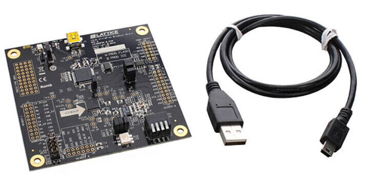
This demo is composed of a host C program the computer compiled on Linux that will communicate with the Lattice ICE40 FPGA UltraPlus Breakout Board., via the FTDI chip on the breakout board. The Lattice ICE40 FPGA UltraPlus Breakout Board. will implement a soft 4 wire SPI slave HDL that will serve of the communication method between the host and the Finite State Machine inside the FPGA. Here us a block diagram of this demo,

The SPI soft-core module is defined in the spi_slave.v Verilog HDL module shown later. Communication is done with packets of 4 Bytes. The first byte is the opcode on the MOSI line, on the MISO it is a status byte. The two other bytes are used for data. These opcodes are implemented:
OPCODE  | Description
0x0     | Nop, does nothing
0x1     | Init, starts the state machine on the fpga side
0x2     | Writes 16bits to be inverted on the fpga
0x3     | Reads the 16 inverted bits on the next communcation
0x4     | Writes led value to be on the breakout board. (RGB, LSB is R)
0x5     | Reads which of the RGB led is on, on the next SPI communication
0x6     | The host computer will send 4*24bits values (vector)
0x7     | Reads the 4*24bits values
The host main.c program is.
#include <stdio.h>
#include "spi_lib.h"

#define SPI_NOP 0x00
#define SPI_INIT 0x01
#define SPI_SEND_BIT_INV 0x02
#define SPI_READ_REQ_BIT_INV 0x03
#define SPI_SET_LED 0x04
#define SPI_READ_REQ_LED 0x05
#define SPI_SEND_VEC 0x06
#define SPI_READ_VEC 0x07

int main()
{
   spi_init();

   uint8_t no_param[3] = {0x00, 0x00, 0x00};
   uint8_t spi_status = 0;
   uint8_t data_read[3];
   uint8_t val_inv[3] = {0x38, 0xAE, 0x3B};

   /*
       assign LED_R = ~led[0];
	   assign LED_G = ~led[1];
	   assign LED_B = ~led[2];

    */
   uint8_t val_led_red[3] = {0x00, 0x0, 0x01};
   uint8_t val_led_yellow[3] = {0x00, 0x00, 0x03};
   uint8_t val_led_green[3] = {0x00, 0x00, 0x02};
   uint8_t val_led_blue[3] = {0x00, 0x00, 0x04};
   uint8_t val_led_purple[3] = {0x00, 0x00, 0x05};
   uint8_t val_led_turquoise[3] = {0x00, 0x00, 0x06};
   uint8_t val_led_white[3] = {0x00, 0x00, 0x07};

   spi_send(SPI_INIT, no_param, NULL); // init

   spi_send(SPI_SEND_BIT_INV, val_inv, &spi_status); // send values bit inversion
   printf("send inversion data, status: 0x%x\n", spi_status);

   spi_send(SPI_READ_REQ_BIT_INV, no_param, NULL); //send read request
   spi_read(data_read, &spi_status); // read data inversion

   for (size_t i = 0; i < 3; i++) {
      printf("bit inversion read idx %i: 0x%x, should be 0x%x\n", i, data_read[i], 0xFF&~val_inv[i]);
   }
   printf("status: 0x%x\n", spi_status);

   spi_send(SPI_SET_LED, val_led_yellow, &spi_status); // led yellow
   printf("send yellow led, status: 0x%x\n", spi_status);

   spi_send(SPI_READ_REQ_LED, no_param, NULL); //send led read request

   spi_read(data_read, &spi_status); // read led data
   printf("led_data read: 0x%x, 0x%x, 0x%x, status:0x%x\n", data_read[2], data_read[1], data_read[0], spi_status);

   //wait 2sec before setting led in blue
   usleep(2000*1000);

   spi_send(SPI_SET_LED, val_led_blue, &spi_status); // set led blue
   printf("send blue led, status: 0x%x\n", spi_status);

   //send 4 values the fastest possible
   for (size_t i = 0; i < 4; i++) {
      int send_value = (i+1)*16;
      spi_send24b(SPI_SEND_VEC, send_value, &spi_status);
      printf("sent vector val: 0x%x, status: 0x%x\n", send_value, spi_status);
   }

   usleep(1000);

   //send read request, the fpga will send the 4 values
   spi_send(SPI_READ_VEC, no_param, &spi_status);
   printf("sent read req vector, status: 0x%x\n", spi_status);

   //read values the fastest possible
   for (size_t i = 0; i < 4; i++) {
      spi_read(data_read, &spi_status);
      printf("vector read: 0x%x, 0x%x, 0x%x, status:0x%x\n", data_read[2], data_read[1], data_read[0], spi_status);
   }


   int delay = 2000*100;

   while(1)
   {
	    spi_send(SPI_SET_LED, val_led_yellow, &spi_status); // led yellow
		//printf("send yellow led, status: 0x%x\n", spi_status);

		//wait 2sec before setting led in blue
		usleep(delay);

		spi_send(SPI_SET_LED, val_led_blue, &spi_status); // led blue
		//printf("send yellow led, status: 0x%x\n", spi_status);

		//wait 2sec before setting led in blue
		usleep(delay);


		spi_send(SPI_SET_LED, val_led_red, &spi_status); // led red
		//printf("send yellow led, status: 0x%x\n", spi_status);

		//wait 2sec before setting led in blue
		usleep(delay);

		spi_send(SPI_SET_LED, val_led_green, &spi_status); // led green
		//printf("send yellow led, status: 0x%x\n", spi_status);

		//wait 2sec before setting led in blue
		usleep(delay);

		spi_send(SPI_SET_LED, val_led_purple, &spi_status); // led purple
		//printf("send yellow led, status: 0x%x\n", spi_status);

		//wait 2sec before setting led in blue
		usleep(delay);

		spi_send(SPI_SET_LED, val_led_turquoise, &spi_status); // led turquoise
		//printf("send yellow led, status: 0x%x\n", spi_status);

		//wait 2sec before setting led in blue
		usleep(delay);


		spi_send(SPI_SET_LED, val_led_white, &spi_status); // led white
		//printf("send yellow led, status: 0x%x\n", spi_status);

		//wait 2sec before setting led in blue
		usleep(delay);


   }

   return 0;
}
After this host program is compiled in Linux the following HDL top.v was used in this demo that implements the Finite State Machine inside the FPGA,
//opcodes:
//0x00 nop
//0x01 init
//0x02 write 16bits inverted
//0x03 read 16bits inverted
//0x04 write leds (16bits LSB)
//0x05 read leds (16bits LSB)
//0x06 write vector, the computer will send 4 * 24bit values
//0x07 read vector, the fpga will send 4 * 24bit values

module top(input [3:0] SW, input clk, output LED_R, output LED_G, output LED_B, input SPI_SCK, input SPI_SS, input SPI_MOSI, output SPI_MISO);

   reg spi_reset;
   wire spi_wr_buffer_free;
   reg spi_wr_en;
   reg [23:0] spi_wr_data;
   wire spi_rd_data_available;
   reg spi_rd_data_available_buf;
   reg spi_rd_ack;
   wire [31:0] spi_rd_data;

   parameter NOP=0, INIT=1, WR_INVERTED=2, RD_INVERTED=3, WR_LEDS=4, RD_LEDS=5, WR_VEC=6, RD_VEC=7;

   spi_slave spi_slave_inst(.clk(clk), .reset(spi_reset),
      .SPI_SCK(SPI_SCK), .SPI_SS(SPI_SS), .SPI_MOSI(SPI_MOSI), .SPI_MISO(SPI_MISO),
      .wr_buffer_free(spi_wr_buffer_free), .wr_en(spi_wr_en), .wr_data(spi_wr_data),
      .rd_data_available(spi_rd_data_available), .rd_ack(spi_rd_ack), .rd_data(spi_rd_data)
   );

   reg [2:0] led;

   reg [31:0] spi_recv_data_reg;
   reg handle_data;

   reg [23:0] reg_bits_inversion;

   reg [23:0] vector [0:4];
   //reg [7:0] vec_ptr;
   reg [2:0] vec_ptr;
   reg sending_vector;

   assign LED_R = ~led[0];
   assign LED_G = ~led[1];
   assign LED_B = ~led[2];

   integer i;

   initial begin

      for(i = 0; i < 4; i=i+1) begin
         vector[i] = 0;
      end

      spi_reset = 0;
      spi_wr_en = 0;
      spi_wr_data = 0;
      spi_rd_ack = 0;

      vec_ptr = 0;
      sending_vector = 0;

      led = 0;
      spi_recv_data_reg = 0;
      handle_data = 0;
   end

   always @(posedge clk)
   begin

      //defaults
      spi_rd_ack <= 0;
      spi_wr_en <= 0;

      spi_rd_data_available_buf <= spi_rd_data_available;

      if(spi_rd_data_available == 1 && spi_rd_data_available_buf == 0) begin // rising edge
         spi_recv_data_reg <= spi_rd_data;
         spi_rd_ack <= 1;
         handle_data <= 1;
      end

      //sends the 4-24bit vector with spi
      if(sending_vector == 1 && spi_wr_buffer_free == 1) begin
         spi_wr_en <= 1;
         spi_wr_data[23:0] <= vector[vec_ptr];
         if(vec_ptr < 3) begin
            vec_ptr <= vec_ptr+1;
         end else begin
            vec_ptr <= 0;
            sending_vector <= 0;
         end
      end

      if(handle_data == 1) begin
         case(spi_recv_data_reg[7:0])
            WR_INVERTED: begin
               reg_bits_inversion[23:0] <= ~spi_recv_data_reg[31:8];
            end
            RD_INVERTED: begin
               spi_wr_en <= 1;
               spi_wr_data[23:0] <= reg_bits_inversion[23:0];
            end
            WR_LEDS: begin
               led[2:0] <= spi_recv_data_reg[26:24];
            end
            RD_LEDS: begin
               spi_wr_en <= 1;
               spi_wr_data[23:0] <= {21'b0 ,led[2:0]};
            end
            WR_VEC: begin
               vector[vec_ptr] <= spi_recv_data_reg[31:8];
               if(vec_ptr < 3)
               begin
                  vec_ptr <= vec_ptr+1;
               end else begin
                  vec_ptr <= 0;
               end
            end
            RD_VEC: begin
               sending_vector <= 1;
            end
         endcase
         handle_data <= 0;
      end
   end

endmodule
The corresponding SPI slave soft HDL file is spi_slave.v
// receive: byte2 | byte1 | byte0 | opcode/status
//read all the data, but can write only the two bytes as opcode contains metadata

module spi_slave(input wire clk, input wire reset,
      input wire SPI_SCK, input wire SPI_SS, input wire SPI_MOSI, output wire SPI_MISO,
      output wire wr_buffer_free, input wire wr_en, input wire [23:0] wr_data,
      output reg rd_data_available, input wire rd_ack, output reg [31:0] rd_data
   );

   reg [4:0] counter_read; //max 32

   reg [1:0] spi_clk_reg;
   reg [1:0] spi_ss_reg;
   wire spi_ss_falling_edge;
   wire spi_ss_rising_edge;

   reg [1:0] mosi_reg;
   reg miso_out_reg;
   reg [7:0] state_rd;

   reg wr_reg_full;
   reg [23:0] wr_data_reg; //written data to send to spi/miso
   reg wr_queue_full;
   reg [23:0] wr_data_queue; //waiting to be written in the register, avoid a write while communcating with SPI

   reg buffer_rd_ack;
   reg [31:0] rd_data_local;

   //states
   parameter IDLE = 0, INIT=IDLE+1, RD_WAIT_DATA=INIT+1, RD_WAIT_ACK=RD_WAIT_DATA+1, WR_WAIT_DATA=RD_WAIT_ACK+1, WR_WAIT_ACK=WR_WAIT_DATA+1;

   assign SPI_MISO = miso_out_reg;
   wire spi_clk_rising_edge;
   wire spi_clk_falling_edge;
   assign spi_clk_rising_edge = (spi_clk_reg[1:0] == 2'b01);
   assign spi_clk_falling_edge = (spi_clk_reg[1:0] == 2'b10);
   assign spi_ss_rising_edge = (spi_ss_reg[1:0] == 2'b01);
   assign spi_ss_falling_edge = (spi_ss_reg[1:0] == 2'b10);

   initial begin
      counter_read = 0;
      spi_clk_reg = 0;
      spi_ss_reg = 0;
      mosi_reg = 0;
      miso_out_reg = 0;
      state_rd = INIT;
      wr_reg_full = 0;
      wr_data_reg = 24'hcafe77;
      wr_queue_full = 0;
      wr_data_queue = 0;

      buffer_rd_ack = 0;
      rd_data = 0;
      rd_data_local = 0;

      rd_data_available = 0;
   end

   assign wr_buffer_free = ((~wr_queue_full) & (~wr_reg_full) & (~wr_en));

   always @(posedge clk)
   begin
      if(reset == 1) begin
         rd_data <= 0;
         rd_data_local <= 0;
         rd_data_available <= 0;
         state_rd <= INIT;
      end else begin

         spi_clk_reg <= {spi_clk_reg[0], SPI_SCK};
         mosi_reg <= {mosi_reg[0], SPI_MOSI};
         spi_ss_reg <= {spi_ss_reg[0], SPI_SS};

         if (spi_ss_falling_edge == 1 || spi_ss_rising_edge == 1) begin
            counter_read <= 0;
         end

         if(spi_clk_rising_edge == 1'b1) begin //default on spi clk
            miso_out_reg <= 0; //default
         end

         case (state_rd)
         INIT : begin // wait the init opcode from host (0x1) and nothing else
            if(spi_clk_rising_edge == 1'b1) begin
               rd_data_local[31:0] <= {mosi_reg[0], rd_data_local[31:1]};
               counter_read <= counter_read + 1;

               if(counter_read == 5) begin //status, write master to slave successful
                  miso_out_reg <= 1;
               end

               if(counter_read >= 31) begin //finish recv
                  if(rd_data_local[8:1] == 8'h1) begin //received init opcode, otherwise ignore
                     state_rd <= RD_WAIT_DATA;
                  end
                  counter_read <= 0;
               end

            end
         end
         RD_WAIT_DATA : begin
            if(spi_clk_rising_edge == 1'b1) begin
               if(counter_read == 5 && rd_data_available == 0) begin //status, write master to slave successful
                  miso_out_reg <= 1;
               end

               if (wr_reg_full == 1) begin //something ready to be written

                  //bits 0-7 reserved for status, starting to write wr_data_reg
                  //one clock before to be sent the next on miso
                  if(counter_read == 6) begin //status, read master to slave successful
                     miso_out_reg <= 1;
                  end else if(counter_read >= 7 && counter_read < 31) begin
                     miso_out_reg <= wr_data_reg[0];
                     wr_data_reg[23:0] <= {wr_data_reg[0], wr_data_reg[23:1]};
                  end
               end

               rd_data_local[31:0] <= {mosi_reg[0], rd_data_local[31:1]};
               counter_read <= counter_read + 1;

               if(counter_read >= 31) begin //finish recv

                  if (wr_reg_full == 1) begin //something was written, now free
                     wr_reg_full <= 0;
                     wr_data_reg <= 24'h00; //clear write buffer
                  end

                  if(rd_data_available == 0) begin
                     rd_data_available <= 1;
                     rd_data <= {mosi_reg[0], rd_data_local[31:1]};
                  end
                  state_rd <= RD_WAIT_DATA;
                  counter_read <= 0;
               end
            end
         end
         default : begin
         end
         endcase

         if(rd_ack == 1 && rd_data_available == 1 && buffer_rd_ack == 0) begin
            buffer_rd_ack <= 1;
         end

         if(buffer_rd_ack == 1 && counter_read == 0) begin
            rd_data_available <= 0;
            buffer_rd_ack <= 0;
         end

         //write to the queue
         if (wr_en == 1 && (~wr_reg_full) && (~wr_queue_full) ) begin
            wr_queue_full <= 1;
            wr_data_queue <= wr_data;
         end

         //move from queue to reg only when no com (counter_read == 0)
         if(wr_queue_full == 1 && counter_read == 0) begin
            wr_data_reg <= wr_data_queue;
            wr_queue_full <= 0;
            wr_reg_full <= 1;
         end
      end
   end
endmodule
The following video shows this demo,
Have a great day!