The LM317 is a classic adjustable voltage regulator from the 1970s. Today, this jellybean part comes in a variety of packages including the SOT23-5, the original TO-220, and the iconic TO-3 package. This engineering brief reviews the LM317’s theory of operation, presents the output voltage derivation, and includes a few gotchas that trip up engineers and technicians.
Note that the LM317 (Figure 1) is a positive output adjustable regulator. The material in this post is directly applicable to the complementary LM337 negative voltage regulator.
![]() Canonical Article: What are jellybean electronic components?
Canonical Article: What are jellybean electronic components?

Figure 1: Classic from the workbench experiment with the LM317 regulator including a paper binder as a heatsink and three type 7268 incandescent lamps as a load.
Internal Operation of the LM317
Figure 2 presents the essential LM317 sections. It includes critical internal components and two external components:
-
Voltage Reference: The LM317 operates using a negative feedback loop where the output voltage is compared to the voltage reference. Stability depends on the quality of the internal 1.25 VDC bandgap reference.
-
Constant current source: The stability of the voltage reference is further improved by using a constant current source. This acts as an electronic shield, isolating the voltage reference from changes in input voltage.
-
Amplifier: An amplifier compares the output voltage to the voltage reference.
-
Pass transistor: The NPN pass transistor as controlled by the op-amp determines the output voltage of the LM317 regulator. The pass transistor is a large device that dissipates power estimated using the equation: P_{Dissipation} = I_{Out}(V_{In} - V_{Out}).
-
Resistor R1 and R2: The external resistors are used to determine the output voltage of the LM317.
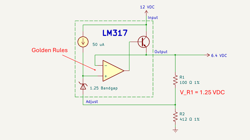
Figure 2: Simplified representation of the LM317 and supporting circuitry.
Theory of Operation
The bottom line is that the voltage, as measured across R1, is maintained at 1.25 VDC.
Golden Rules for an Op-amp
To understand the LM317’s operation, we first consider the golden rules for op-amp operation as described by Horowitz and Hill in their famous Art of Electronics book:
-
Rule 1: The output will do whatever is necessary to make the difference between the inputs zero.
-
Rule 2: The inputs draw no current.
If we apply these rules to the simplified Figure 2 schematic, we conclude that the voltage across R1 is the same as the voltage reference (1.25 VDC). This R1 = 1.25 VDC is key to the operation of the LM317.
How the LM317 Senses Output Voltage
The output voltage of the LM317 is not ground referenced. Instead, it is implicitly measured as the voltage drop across R1.
Recognize that feedback keeps the R1 voltage constant at 1.25 VDC. A constant voltage across a fixed R1 resistor results in a fixed current. Finally, we intuit that R2’s current is also constant (disregarding the relatively insignificant current flowing in the LM317’s adjust terminal).
Derivation of the Output Voltage Equation
Essential facts from Figure 2:
-
The op-amp maintains R1 voltage equal to the reference voltage (1.25 VDC)
-
The op-amp input draws no current.
-
The current leaving the LM317’s adjust terminal is insignificant relative to the current passing through R1 and R2. Consequently, the R1 and R2 currents are equal.
-
A current of approximately 5 mA is required to maintain the NPN transistor in its linear (active) state.
Knowing that I_R1 = I_R2:
I_{R1} = \frac{V_{REF}}{R_1}
I_{R2} = I_{R1} = \frac{V_{REF}}{R_1}
V_{OUT} = I_{R1}(R_1 + R_2) = \frac{V_{REF}}{R_1}(R_1 + R_2) = V_{REF}\!\left(1 + \frac{R_2}{R_1}\right)
Choosing R1
Resistor R1 must be less than 250 Ω to ensure the pass transistor operates in its linear region. But not too small, as it needlessly burns power. We often see R1 bounded between 100 Ω and 250 Ω.
Design Errors and Other Gotchas for the LM317
Overheating from Excessive Power Dissipation
The LM317 is a linear regulator. The current through the pass element is the same as the current passing through the load (plus a little more for R1 / R2 combination). The power dissipation is estimated as:
P_{Dissipation} = I_{Out}(V_{In} - V_{Out}).
Semiconductor cooling is a topic unto itself. To get started, refer to this article to understand the critical difference between ambient (T_A), case(T_C), and junction (T_J) temperatures.
Tech Tip: Include enough heatsink to cover the worst-case situation where both input voltage and load current are high. Watch out for line voltage (typically +/- 5%) which could be higher such as when your product is powered from a modified sine converter or a generator with poor voltage regulation.
Yes, the LM317 has overtemperature protection, but Murphy’s law is not on your side. Don’t depend on this built in safety feature.
Ignoring the Adjust Pin Current
There is an error with the previously defined output equation as it discounts the small current passing through the LM317’s adjust terminal. This is insignificant provided we select an R1 less than 250 Ω.
Poor Regulation at Low Load Current
The LM317’s output transistor requires about 5 mA to operate in its linear state. Once again, we solve this by keeping R1 low, typically between 100 and 250 Ω. At 100 Ω the load current is about 12.5 mA which heats up the LM317. For example, an LM317 with a 15 VDC input and a 9 VDC output dissipates 75 mW in the chip plus another 113 mW wasted in R1 and R2. There isn’t much wiggle room for R1.
Using Typical Instead of Maximum Specifications
The minimum load current is not a universal 5 mA. Some LM317s operate as low as 3.5 mA while others may require up to 10 mA.
Be sure to differentiate between the datasheet’s “typical” and “maximum” specifications. A 3.5 mA device with a 10 mA maximum should be operated at 10 mA to faithfully maintain regulating.
Excessive Voltage when the Feedback Path Fails
The classic LM317 circuit includes a variable resistor in the R2 position. There is a hazard as this potentiometer ages. Specifically, as the wiper ages, it will become noisy or momentarily fail resulting in an open circuit (Ω = ∞). Analysis of the output equation shows that the output voltage will jump to the input voltage minus the overhead of the regulator.
This feedback failure can damage sensitive components. If the wiper fails or becomes noisy, nearly the full rail voltage is applied to the output. For example, a LM317-based bench power supply with a 20 VDC input rail will smoke a 3.3 VDC logic chip.
We can provide limited protection by:
-
Wire the variable resistor body (terminals 1 and 3) into the circuit as shown in Figure 3. Stated another way, don’t let resistor pin 3 float.
-
Add a Zener diode clamp across R2. This will conduct when the wiper fails thereby limiting voltage to V_zener + 1.25 VDC.
-
Use a variable resistor in parallel with a fixed resistor (Figure 3) to limit the total voltage excursion and the variable trimmer to perform the fine adjustments.
-
Use a small value potentiometer to limit the total voltage excursion with terminals 1 and 3 permanently connected to the circuit.
-
Add a crowbar circuit to shunt the output voltage. This is a brutal solution with high potential to damage the LM317, but it will save your sensitive load.

Figure 3: Partial schematic and image of the variable power supply with protection against variable resistor wiper failure.
Oscillation or Damage Without Capacitors and Protection Diodes
A complete LM317 circuit includes protection diodes and capacitors as shown in the Texas Instruments schematic (Figure 4). The capacitors reduce noise and help reduce oscillations. The diodes prevent damage against reverse current flow.
Refer to the datasheet for recommended components and additional application circuits.

Figure 4: Complete LM317 circuit as shown in a Texas Instruments datasheet.
Example Application #1: 6.4 VDC Fixed Output Supply
For this example, we will configure the LM317 for an output voltage of 6.4 VDC to mimic two lithium-ion batteries connected in series. The resistor values are shown in Figure 2 where 1% tolerance R1 is 100 Ω and R2 is 412 Ω.
Selecting the Resistor Pair
Recall that two resistors are required to set the LM317’s output voltage. Since resistors are only available in discrete steps, we must find a valid pair that sets the desired output voltage while balancing quiescent current.
Given a desired output voltage of 6.4 VDC we solve for the R2 to R1:
V_{OUT} = 6.4 = V_{REF}\!\left(1 + \frac{R_2}{R_1}\right)
It follows that:
\frac{R_2}{R_1} = 4.12
We can refer to this article to help us with the selection process. The document presents a graphical method to locate the resistor pair as well as a computer program.
This example was relatively easy as both 1.00 and 4.12 are found in the E-192 (1% tolerance) resistor series.
Tech Tip: Output voltage tolerance is directly related to the tolerance of R1 and R2. Recommend using 1% tolerance or better for fixed output voltage regulators. In this example, the output voltage measured as 6.38 VDC with my trusty multimeter. For better results I would need to obtain a better multimeter and shift to 0.1% tolerance resistors.
Example Application #2: Variable Supply with Overvoltage Limits
In our second example we construct a supply with variable output with a hard limit to prevent overvoltage in the case of a variable resistor wiper failure. We replace R2 with a fixed resistor in parallel with a variable resistor such that the output voltage can go no higher than approximately 8 VDC. The resulting partial schematic and picture are included as Figure 3.
Working backwards from the chosen 8 VDC maximum output voltage:
V_{OUT} = 8.0 = V_{REF}\!\left(1 + \frac{R_2}{R_1}\right)
It follows that:
\frac{R_2}{R_1} = 5.40
Resistor R1 is retained at 100 Ω. Consequently, the parallel resistance for the composite R2 is 540 Ω.
We select a standard 2 kΩ variable resistor.
The resulting fixed resistor is approximately 740 Ω. The nearest convenient E24 (5% tolerance) value is 750 Ω.
History of the LM317
The LM317 was designed by Bob Dobkin in the 1970s. Instead of writing about the design, let’s listen to Bob himself as he describes the LM317 as one of his favorite circuits (time index 58:45 in Video 1). Watch how Dobkin lights up when talking about the 50 year old LM317 and the newer LT3080
The process technology gave me the parts I needed and 30 years more experience gave me the design experience I needed.
Figure 5 shows a modern TO-220 packaged LM317 next to an LT3080. Note that the LT3080 uses a single resistor to set the output voltage. The regulator is also adjustable all the way down to 0 VDC.

Video 1: Oral History with Analog Designer Bob Dobkin.

Figure 5: Image of an LM317 next to an LT3080.
Locating the LM317 in DigiKey
Like other jellybean components, the LM317 is properly identified as the head of a large number of related components. The best way to search DigiKey is to use a compound search with keywords “317 regulator”. As of October 29, 2025, the DigiKey search engine returns hundreds of related devices ranging from SOT23-5 to TO-220, to TO-3 packages. Likewise, the complementary “337 regulator” returns another hundred.
Parting Thoughts
I should have added that jellybean parts are fun. Many of us learned electronics by building a simple bench power supply featuring the LM317. I remember cutting the sheet metal, using a heatsink from an old TV, and adding the banana jack. This classic project is every bit as relevant for today’s learner as it was nearly a half century ago.
Let’s see if the pattern holds for another 50 years.
Best wishes,
APDahlen
Related Articles by this Author
If you enjoyed this article, you may also find these related articles helpful:
- Is the 2N3904 transistor obsolete?
- Circuit Myths: MOSFETs Require No Gate Current
- Circuit Myths: Maximum Power Transfer Theorem
- Calculating the Operational Life of an Aluminum Electrolytic Capacitor
About This Author
Aaron Dahlen, LCDR USCG (Ret.), serves as an application engineer at DigiKey. He has a unique electronics and automation foundation built over a 27-year military career as a technician and engineer which was further enhanced by 12 years of teaching (interwoven). With an MSEE degree from Minnesota State University, Mankato, Dahlen has taught in an ABET-accredited EE program, served as the program coordinator for an EET program, and taught component-level repair to military electronics technicians.
Dahlen has returned to his Northern Minnesota home, completing a decades-long journey that began as a search for capacitors. Read his story here.