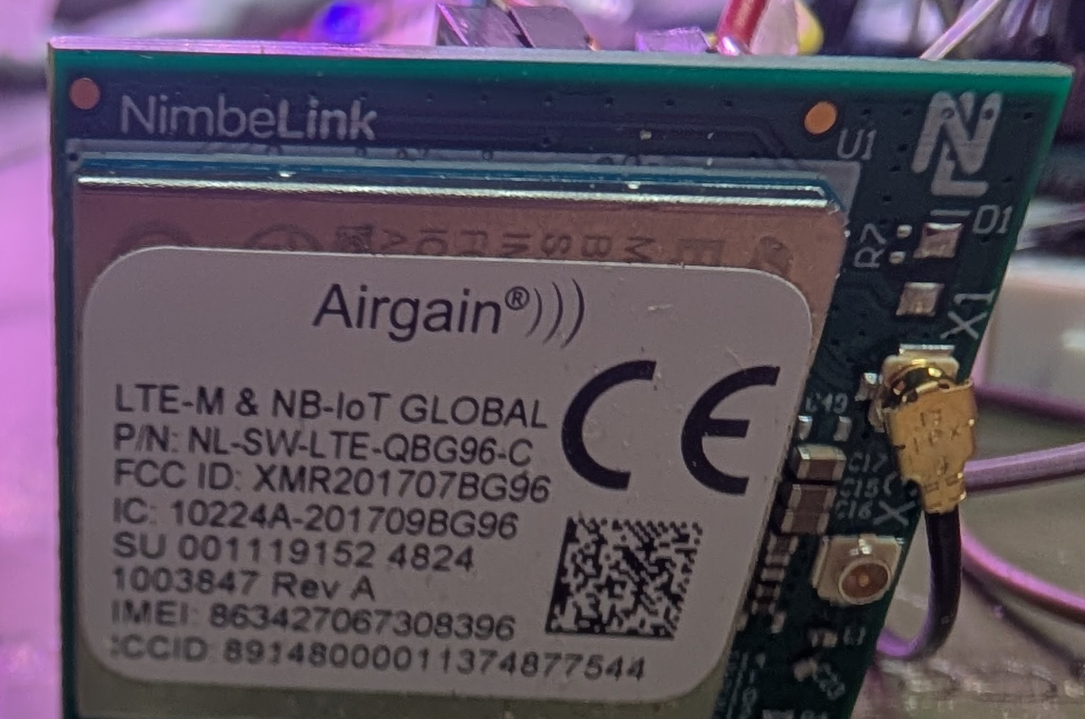
I purchased an LTE QGB96 (Airgain) device (1-20 pins). I am having difficulty sending and receiving AT commands from my Arduino sketch, so I was advised to buy a TTL-232R-3V3 USB Embedded UART 3.3V cable
.1 "HDR. The cable arrived, but I need guidance on how to interface the two for diagnostics.
Any help is appreciated.
Would you have the DigKey item numbers for both the device and the cable that you reference?
This will let us review the correct items that you have on hand.
DigiKey Part Number
1477-NL-SW-LTE-QBG96-C-ND
Manufacturer
Airgain
Manufacturer Product Number
NL-SW-LTE-QBG96-C
Description
RF TXRX MODULE CELL/NAV U.FL TH
DigiKey Part Number
768-1015-ND
Manufacturer
FTDI, Future Technology Devices International Ltd
Manufacturer Product Number
TTL-232R-3V3
Description
CABLE USB EMBD UART 3.3V .1"HDR
I think this is what I am looking for. Will the TX be at the 3.3v level rather than 5v?
Correct, the TTL-232R-3V3 logic level is 3.3v…
Looks like you directly access the modem with pins 2, 3 and 4…
Regards,
Is pin 1 (grnd) and 3 (vcc) supposed to power up the QGB96 via port 1 (vcc) & 4 (grnd)? Not working for me.
Please don’t connect VCC from the TTL-232R-3V3 as it’s “VCC” from the USB bus (5v)..
TTL-232R-3V3 only changes the serial pins to be 3v3 tolerant.
Vcc (5v) can only source 75mA
J1 pinout:
Regards,
Btw, which Arduino platform did you try to use when sending AT commands?
If your plugging into an Arduino, this kit would be very useful to make sure the voltages are proper: NL-SWDK2 Airgain | Development Boards, Kits, Programmers | DigiKey
Regards,
1 Like
I like the kit. I am using an Uno with the following sketch:
#include <SoftwareSerial.h>

SoftwareSerial bg96(8, 7); // RX, TX: D8 ← BG96 TX, D7 → BG96 RX via level shifter

const int pinOnOff = 5;     // Controls BG96 ON_OFF (Pin 20)
const char* phoneNumber = "+xxxxxxxxxx";
const char* smsText = "Hello from BG96 via 1NCE!";
bool smsSent = false;

void setup() {
  Serial.begin(9600);
  bg96.begin(9600);
  Serial.println("Powering up BG96...");

  pinMode(pinOnOff, OUTPUT);
  digitalWrite(pinOnOff, LOW);
  delay(200);
  pinMode(pinOnOff, INPUT); // Let pull-up to 3.3V take over

  delay(5000); // Wait for BG96 to boot

  initializeModem();
}

void loop() {
  static unsigned long startTime = millis();

  while (bg96.available()) {
    Serial.write(bg96.read());
  }

  if (!smsSent && millis() - startTime >= 60000UL) {
    sendSMS(phoneNumber, smsText);
    smsSent = true;
  }
}

void initializeModem() {
  sendCommand("AT");
  sendCommand("ATE0");
  sendCommand("AT+CPIN?");
  sendCommand("AT+CSQ");
  sendCommand("AT+CREG?");
  sendCommand("AT+CGATT?");
  sendCommand("AT+CMGF=1");
  sendCommand("AT+CSCS=\"GSM\"");
}

void sendSMS(const char* number, const char* text) {
  Serial.println("Sending SMS...");
  bg96.print("AT+CMGS=\"");
  bg96.print(number);
  bg96.println("\"");
  delay(1000); // Wait for >
  bg96.print(text);
  bg96.write(26); // Ctrl+Z to send
  Serial.println("SMS sent command issued.");
}

void sendCommand(const char* cmd) {
  Serial.print("→ BG96: ");
  Serial.println(cmd);
  bg96.println(cmd);
  delay(500);
}
Can I attach my sensors to the kit? My project uses three different vibration sensors and an sms message is sent if vibration is detected.
What and how may interfaces do these sensors use? i2c/spi/uart/etc? Pins/etc?
Regards,
1 Like
They use pins A0-A2. Simple Analog sensors
You would lose A0 with this Arudino shield.
Regards,
1 Like
Alright.. I will move to digital sensors instead… Thanks