This section covers the setup of the enclosure, the PLC and it’s connected components. For the hardware needed please review the Hardware Selection.
Setup
Before the installation of the of the components, the enclosure will need to be modified. Below are the drawings that have the dimensions for the modifications needed for the inner panel and enclosure. The step drill bits from Klein are used for these modifications.
Inner Panel Modifications (100.0 KB)
EN4SD20168GY Modified (111.6 KB)

With the holes drilled, the DIN rail can now be installed. The DIN rail is will be installed on the top, middle and bottom sections of the inner panel, while the remaining two sections will have the raceway. The M4 screw, lock washer and nut are used to secure the DIN rail and the raceway.
With the DIN rail and raceway installed, the circuit breaker and terminal blocks can be installed.
Terminal Block Installation

The above shows the installation of a terminal block onto DIN rail and the insertion of the ferrule terminated wire into the terminal block.
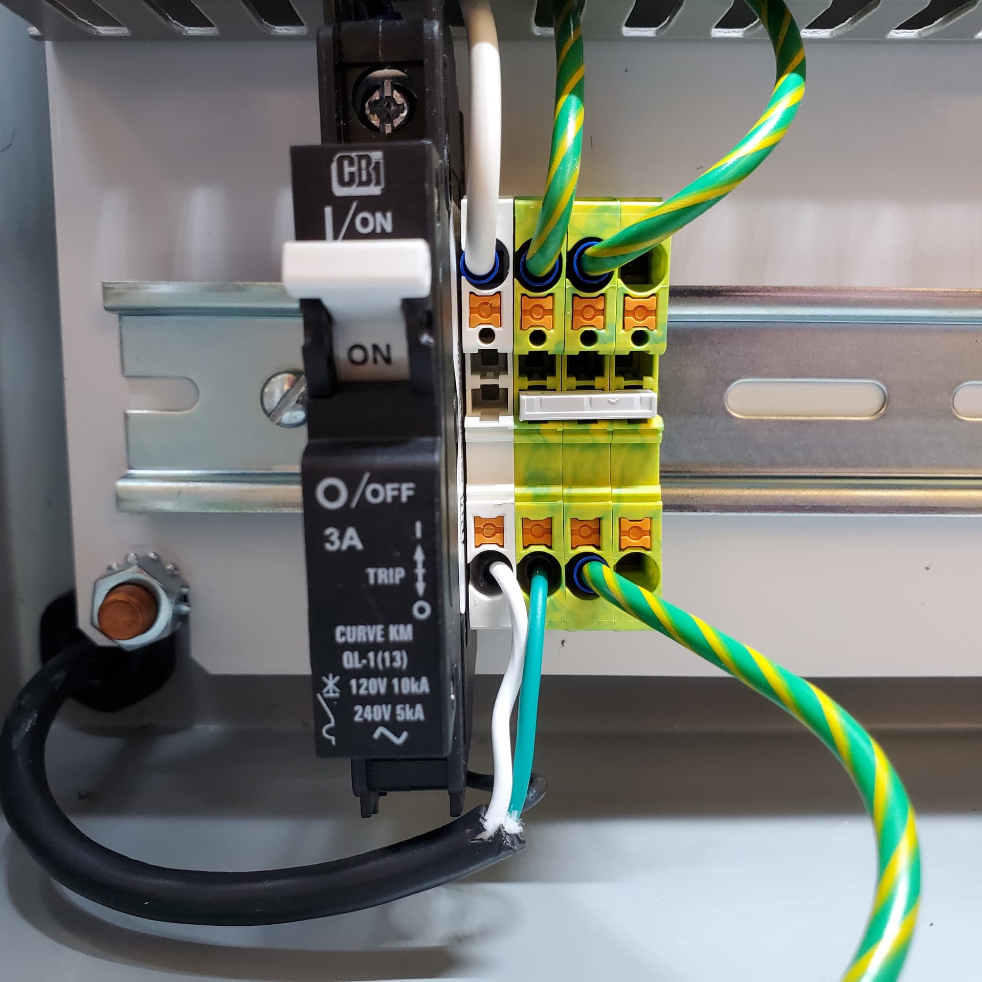
Starting in the bottom left, the circuit breaker 9926251003, White terminal block 3211778 and the Green/Yellow 3211766 are installed. The gray three position jumper is installed across the green/yellow terminal block.

The next set is for 24VDC power and is a set of 16 black terminal blocks, 3211776, half of these will be jumped together for negative and the other half for positive voltage.
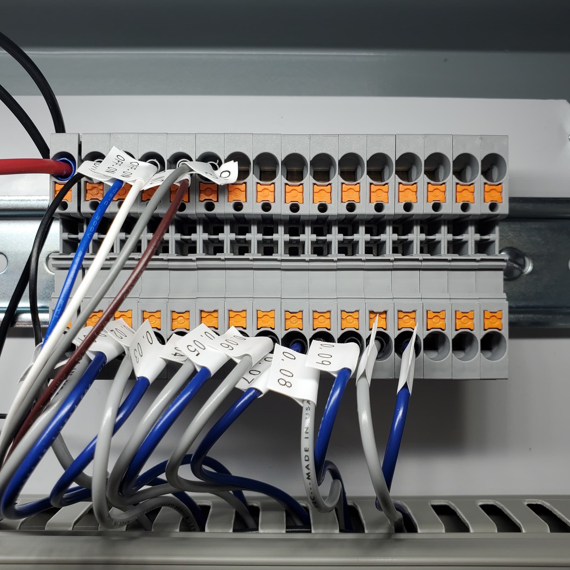
The third set is for the input connections into the PLC there are 16 gray terminal blocks, 3211757, in this set.
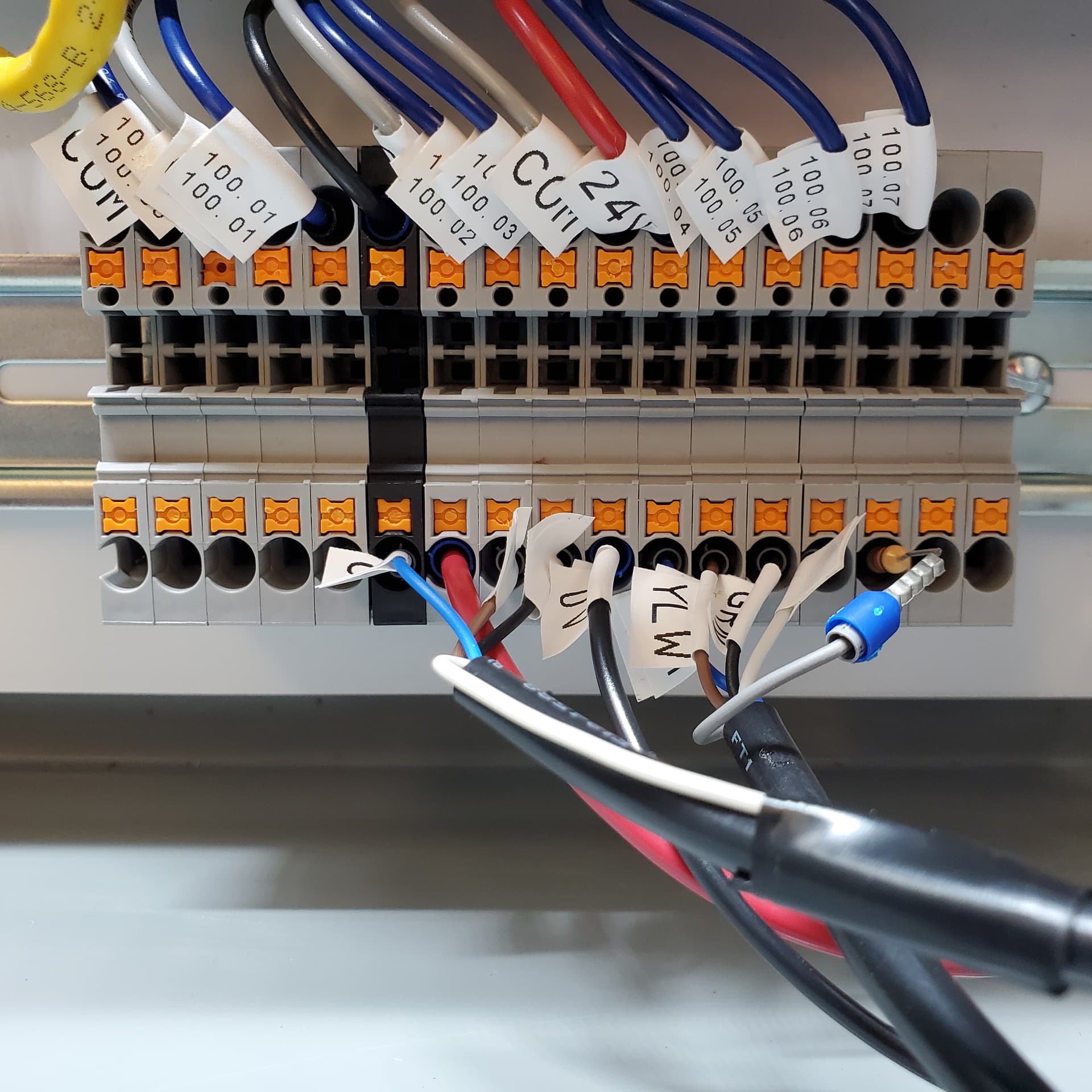
The fourth set is for the output connections from the PLC, there are 15 gray terminal blocks, 3211757, in this set. Additional black terminal blocks can be added to this set to provide power for the outputs.
Once the terminal blocks have been connected to the DIN rail, the power supply and the PLC can be attached to the middle DIN rail.
Wire Terminations & Connections
With the terminal blocks, PSU and PLC installed onto the DIN rail, it is time to connect them to each other. The 14 AWG wire is used for 120VAC and Earth Ground and the 16 AWG is used to connect the 24VDC power and the I/O connections. The wires will need the contacts to be crimped first, before they are connected to the terminal blocks. The chart below shows the length that is needed for each wire and it’s termination. The cables from Banner and Omron will also need the ferrule, 3060-06050D, crimped to each wire.
| Length | AWG | From | To | Color | Quantity | Connection |
|---|---|---|---|---|---|---|
| 8" | 14 | Ferrule | Ferrule | Black | 1 | AC Live |
| 9" | 14 | Ferrule | Ferrule | White | 1 | AC Neutral |
| 9" | 14 | Ferrule | Ferrule | Green/Yellow | 1 | ⏚ to PSU |
| 9" | 14 | Ferrule | .25 Ring | Green/Yellow | 1 | ⏚ to Enclosure |
| 9" | 14 | .25 Ring | .25 Ring | Green/Yellow | 1 | Enclosure to Door |
| 26" | 14 | Ferrule | M3.5 Spade | Green/Yellow | 1 | ⏚ to PLC |
| 8" | 16 | Ferrule | Ferrule | Red | 1 | PSU to Power + |
| 8" | 16 | Ferrule | Ferrule | Black | 1 | PSU to Power - |
| 8" | 16 | Ferrule | M3.5 Spade | Blue | 8 | PLC to Output |
| 8" | 16 | Ferrule | M3.5 Spade | Gray | 8 | PLC to Output |
| 9" | 16 | Ferrule | M3.5 Spade | Blue | 8 | Input to PLC |
| 9" | 16 | Ferrule | M3.5 Spade | Gray | 8 | Input to PLC |
| 14" | 16 | Ferrule | M3.5 Spade | Red | 1 | Power + to PLC |
| 14" | 16 | Ferrule | M3.5 Spade | Black | 1 | Power - to PLC |
As the wire terminations are completed it is best to apply the wire-marker labels to them to keep them organized.
Using the M210 printer with 1/2" labels:
- Select the WireMarker label type
- Set font size to Auto
- Input label text
- Print and Cut
| Label Text | Quantity |
|---|---|
| COM | 6 |
| ⏚ | 4 |
| Live | 1 |
| Neutral | 1 |
| 24VDC | 2 |
| 0VDC | 2 |
| 0.00-0.11 | 1 of each |
| 100.00-.07 | 1 of each |
| NET | 1 |


The AC power enters the enclosure through one of the mounting holes in the enclosure. Heyco part M3243 provides strain relief to the cable. The cable is then wired to the circuit breaker, white and green/yellow terminal block.
PLC
The Omron CP2E-N30DR-D PLC has 18 digital input and 12 relay outputs. The inputs all share a common that is either connected to the Positive or Negative power terminal block. The outputs do not share a common, as see below the PLC has bold lines showing the separation of the commons and the outputs they are connected to. The PLC indicates which inputs and outputs are active.

Sensor Installation
As the E3FA-RN21 is a NPN sensor the common on the PLC will need to be wired to the 24VDC power block. This will also define future types of sensors that can be connected to the PLC. For this PLC build the sensor will be configured as Dark-On.

A larger section of the outer jacket will need to be removed to provide enough length for the wire terminations to reach the power and input 0.00 terminal blocks. When powered the sensors indication light will change according to the configuration.

The connecting cable between the terminal block and the sensor is passed through a cable gland in the enclosure. The sensor is mounted into the bracket and can be mounted to a wall or in this case the door frame with two command strips, 17022-ES. The command strips are also used to mount the reflector.
Tower Light Setup

The Banner tower light TL50CGYRAOSIQ is mounted to the enclosure with the SMB30A bracket. The 5 position M12 cable is passed through a cable gland, just light the sensor. Power needs to be brought down to the output terminal blocks to connect the output. As the tower light is bimodal for power, it can either sink or source. For the demonstration purpose a 4.7K Ohm resistor is placed in-line with the alarm connection, dropping the alarm volume.

The tower is mounted to the side of the enclosure with SMB30A mounting bracket. For additional information, mounting brackets and cables, check out the forum post highlight.
The next section covers the programming the PLC with Ladder Logic.