We use cookies to provide our visitors with an optimal site experience. View our privacy notice and cookie notice to learn more about how we use cookies and how to manage your settings. By proceeding on our website you consent to the use of cookies.
DigiKey support,
I was told by STMicroelectronics that I could get technical assistance on this site for their VL6180X laser sensor device.
I get good distance measurements using an Arduino sketch but can’t use that platform on my final product. Instead I’m using a pic18f46k22 microcontroller but the measured value of the distance at register 0X62 always reads zero.
The device is configured exactly as shown in the Arduino_VL6180X.cpp file and I can successfully read the VL6180X slave address at register 0x212. All voltages for the sensor are 3.3.
I have used a pic and I2C with other devices and I’m getting all the acknowledgements with the VL6180X.
My code for reading the measurement is:
int readDistance(void)
{
int distance = 0;
I2C_Master_Start();
I2C_Master_Write(0x29 << 1);  // TOF050C I²C address write
I2C_Master_Write(0x18);       // VL6180X_REG_SYSRANGE_START
I2C_Master_Write(0x01);       // start a distance measurement
\__delay_us(100);              // wait for measurement to complete

I2C_Master_RepeatedStart();
I2C_Master_Write(0x29 << 1);  // TOF050C I²C address write
I2C_Master_Write(0x62);       // register to read distance
I2C_Master_RepeatedStart();
I2C_Master_Write((0x29 << 1) | 1); // TOF050C I²C address read
distance  = I2C_Read_Byte(1); // Read the measured distance
I2C_Master_Stop();
return (distance);
}  // end unsigned int readDistance(void)
Since you have working Arduino code that you are trying to replicate, it would be a great help if you could share that with us as well. Am I correct in assuming that you are using the Adafruit VL6180 Library? Adafruit_VL6180X.cpp was the closest in name I could find to the “Arduino_VL6180X.cpp” file you mentioned.
Also, can you explain why you are only waiting 100us before attempting to read the range measurement? I may be missing something, but Section 2.7.1 of the VL6180 datasheet suggests it should take on the order of milliseconds for a single range measurement to complete, especially with averaging. I would suggest polling bit 2 of the VL6180X_REG_RESULT_INTERRUPT_STATUS_GPIO register as done in the Adafruit library instead of a simple delay.
uint8_t Adafruit_VL6180X::readRange(void) {
  // wait for device to be ready for range measurement
  while (!(read8(VL6180X_REG_RESULT_RANGE_STATUS) & 0x01))
    ;

  // Start a range measurement
  write8(VL6180X_REG_SYSRANGE_START, 0x01);

  // Poll until bit 2 is set
  while (!(read8(VL6180X_REG_RESULT_INTERRUPT_STATUS_GPIO) & 0x04))
    ;

  // read range in mm
  uint8_t range = read8(VL6180X_REG_RESULT_RANGE_VAL);

  // clear interrupt
  write8(VL6180X_REG_SYSTEM_INTERRUPT_CLEAR, 0x07);

  return range;
}
In the Arduino sketch I do use the Adafruit_VL6180X.cpp. But in my pic microcontroller program I don’t have a library.
I missed that spec in the data sheet about 3.2 ms between reads. The device I was working with suggested much less. I’ll update my code and try it.
In the long run I have to read nine of these sensors in sequence and then do some code. After that’s complete I will wait enough time to not re-read any sensor before about 30ms.
I’ll let you know the results. It may be a few days.
Jerry
Matt_Mielke,
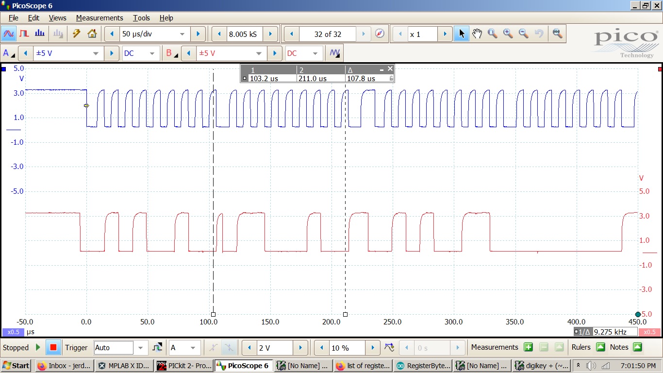
Finally updated my code to wait 4ms between readings and got some scope shots.
START.jpg are the waveforms for the first three steps that initiate a measurement.
READ.jpg are the waveforms for the last four steps that read the distance.
I placed the time measurement lines on the 9th clock to show the acknowledgements. According to the data sheet this should be enough to get a reading but as you can see I just get zero.
Here’s the code:
int readDistance(void)
{
int distance = 0;
I2C_Master_Start();
I2C_Master_Write(0x29 << 1); // TOF050C I²C address write
I2C_Master_Write(0x18); // VL6180X_REG_SYSRANGE_START
I2C_Master_Write(0x01); // start a distance measurement
I2C_Master_Stop();
__delay_ms(4); // wait for measurement to complete
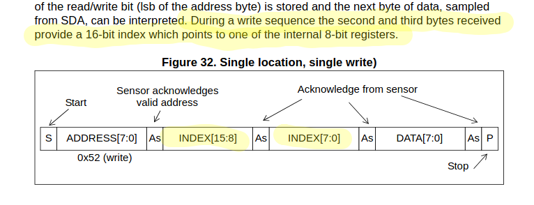
I assume this is why you were able to read the slave address at register 0x0212. You had to use 16-bit indexing to communicate this higher address to the sensor.
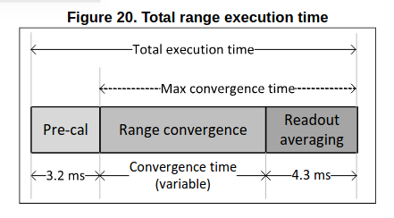
I’d also like to point out that 4ms is likely not going to be a long enough delay to allow the ranging to complete. The datasheet shows that the pre-calibration time plus the readout averaging period alone will take 7.5ms (assuming you haven’t changed the default averaging period). On top of this, you have to allow for the range convergence time, which Table 11 indicates may take anywhere from 180us up to nearly 11ms! Figure 20 summarizes this nicely.
I’ll point out again that best practice in this scenario it to utilize the interrupt flags within the sensor to determine when the measurement is complete. This simplest way to do this is by polling the interrupt status register and waiting for the New Sample Ready bit to be set (see the Adafruit code I posted previously). You could also configure the sensor’s GPIO to generate an external interrupt on the PIC, but that requires significantly more effort to get working properly.
Matt_Mielke,
I have run into another problem with a VL6180X laser sensor.
Since you pointed out that the registers have 16 bid addresses I can successfully read distances.
For cross checking I do this with an Arduino and with a pic microcontroller. The problem is the Arduino can measure down to 2cm but the pic only 10cm. I have configured the registers in the pic as they are in the Arduino. The power and I2C voltages are the same. Each has a 1000ms delay between reads.
My project will require the pic and it has to measure distances down to 2cm.
I can’t find anything in the data sheet to explain this.
I have attached the I2C code for the pic and the Arduino sketch.
Sure, I’ll look though your code here soon. In the meantime, it might speed things up if you could provide a bit more detail about the behavior you’re experiencing.
How exactly does the data become inaccurate below these ranges? Does it stop changing, drop down to 0, or just become progressively inaccurate? Any chance you could provide some serial output which clearly demonstrates the issue?
Thanks, I can see the Arduino video now. The emails you send don’t come to me, but rather are posted as replies to the TechFourm thread you created. If you scroll through, I think you’ll see that the first video link didn’t come through for some reason… Could you re-share the link when you get a chance?
I looked at the code you provided and I’m not seeing what might be causing the issue you described. It’s possible something may have gone awry in the sensor initialization. If you attach the PIC code used to initialize the L6180X, I’d be happy to double check it for you.
Sorry to leave you hanging, but I’m on vacation this week. I’ll be more responsive when I return on Monday.
I’ve already looked through all of your posts, including the flagged ones that were later unflagged. As far as I can tell, nothing other that what is shown on this thread is available to us. So, my current advice remains the same as my previous advice.
Please re-share the video link you’d like me to take a look at.
I encourage you to provide the PIC code used to initialize the L6180X. A second set of eyes couldn’t hurt…
Matt_Mielke,
Sorry I didn’t know you were on vacation.
I tried to send you my pic initialization code but got this message:
“Your post was flagged as spam: the community feels it is an advertisement, something that is overly promotional in nature instead of being useful or relevant to the topic as expected.”
It just had my routine and a shared link to my picReadings.mp4.
I’ll send another one but I’ll probably need another site to send it to.
Just enjoy your vacation and Thanksgiving and we’ll pick this up next week.
Ah, thanks for sharing the auto response you received. One of the Forum admins was able to recover the links you sent. I can now view the picReadings.mp4 video. However, the PIC initialization code has not been made public, so I’m getting an access denied error. If you could make it public, that’d be great.
I just want to make sure, you did verify the sensor’s accuracy at greater distances using a ruler, correct? So when the target (in this case, the box) is exactly 100mm away, you get a reading of 100mm when using both the Arduino and the PIC? There’s no offset with either setup?
Matt,
The Arduino readings are linear from about 70 mm (3 inches) to 200 mm (8 inches) then it returns 255. All the readings are about 20 mm (0.8 inches) long. Below 3 inches the readings still decrease linearly but are long by 40 mm (1.8 inches).
My fixture always returns 28 mm until the target is 128 mm (5 inches) away from the sensor. Then it starts returning linear values from 29 mm (1.4 inches) out to 160 mm (10 inches) then it returns 255.
Same sensor, same target material. The material is flat, gray and I tried to get it as perpendicular to the sensor as I could.
I don’t manipulate the readings from either fixture.
Looking at the Arduino I2C waveforms I did note that they don’t provide any delay after sending the start signal?
Sound to me like neither setup is working as it should be. Sure the PIC is behaving worse, but the Arduino readings are still way farther off then they should be. What happens if you run Adafruit’s example code without modification? Do you still get ranging errors around 20-40mm?