The present article describes how to connect and use multiple Analog Devices DS18B20 temperature sensors concurrently. One of the nice features of this sensor is the 1-Wire communication protocol interface with CRC data integrity checks. This particular 1-Wire interface derives the energy used from the data line itself, therefore eliminating the typical need of an external power source line. With a unique 64-Bit Lasered ROM Code,

multiple of these temperature sensors can share the 1-Wire bus concurrently. A system can control many of these DS18B20s distributed over a huge area. Applications that can benefit from this feature include temperature environmental monitoring, temperature control inside buildings, industrial equipment, or machinery, process monitoring and control systems.
The main features of the Analog Devices DS18B20 temperature sensors are:
• Unique 1-Wire® Interface Requires Only One Port Pin for Communication
• Reduce Component Count with Integrated Temperature Sensor and EEPROM
• Measures Temperatures from -55°C to +125°C (-67°F to +257°F)
• ±0.5°C Accuracy from -10°C to +85°C
• Programmable Resolution from 9 Bits to 12 Bits (Configuration Register)
• No External Components Required Parasitic Power Mode Requires Only 2 Pins for Operation (DQ and GND)
• Simplifies Distributed Temperature-Sensing Applications with Multidrop Capability
• Each Device Has a Unique 64-Bit Serial Code Stored in On-Board ROM
• Flexible User-Definable Nonvolatile (NV) Alarm Settings with Alarm Search Command Identifies Devices with Temperatures Outside Programmed Limits
• Available in 8-Pin SO (150 mils), 8-Pin µSOP, and 3-Pin TO-92 Packages
The 3 Analog Devices DS18B20 temperature sensors used using for this demo are in TO-92 form factor as shown below,

The block diagram of the Analog Devices DS18B20 temperature sensor as follows:

The core functionality of the DS18B20 is its direct-to digital temperature sensor. The resolution of the temperature sensor is user-configurable to 9, 10, 11, or 12 bits (via Configuration Register), corresponding to increments of 0.5°C, 0.25°C, 0.125°C, and 0.0625°C, respectively. The default resolution at power-up is 12-bit. The DS18B20 output temperature data is calibrated in degrees Celsius; for Fahrenheit applications, a lookup table or conversion routine must be used. The temperature data is stored as a 16-bit sign-extended two’s complement number in the temperature register as shown in the next table,

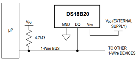
The DS18B20 can also be powered by the conventional method of connecting an external power supply to the VDD pin as shown in the following block diagram if needed,
The DS18B20 internal memory layout is shown below,

The memory consists of an SRAM scratchpad with nonvolatile EEPROM storage for the high and low alarm trigger registers (TH and TL) and configuration register. Note that if the DS18B20 alarm function is not used, the TH and TL registers can serve as general-purpose memory.
After the bus master has used a ROM command (0x55) to address the DS18B20 with which it wishes to communicate, the master can issue one of the DS18B20 function commands. These commands allow the master to write to and read from the DS18B20’s scratchpad memory, initiate temperature conversions and determine the power supply mode. The DS18B20 function commands are shown in the next table,

The following setup was used in this demo with Raspberry Pico 2 W, providing 3.3 V via Pin 36, “ground” reference via Pin 38, the 3 Analog Devices DS18B20 temperature sensors and 3.3 V pull up resistor in GPIO 15 (Pin 20) as the 1-Wire Data Bus,

Three Analog Devices DS18B20 temperature sensors were placed in the 1-Wire bus to demonstrate the concurrency capability of these DS18B20 devices. A Raspberry Pico 2 W platform was used using internal PIO state machine onewire_library.pio to create the customized 1-Wire communication protocol interface and was accessed via an C application using the C SDK. Here is the onewire_library.pio PIO state machine definition file used in this demo,
;
; Copyright (c) 2023 mjcross
;
; SPDX-License-Identifier: BSD-3-Clause
;

; Implements a Maxim 1-Wire bus with a GPIO pin.
;
; Place data words to be transmitted in the TX FIFO and read the results from the
; RX FIFO. To reset the bus execute a jump to 'reset_bus' using the opcode from
; the provided function.
;
; At 1us per cycle as initialised below the timings are those recommended by:
; https://www.analog.com/en/technical-articles/1wire-communication-through-software.html
;
; Notes:
;   (1) The code will stall with the bus in a safe state if the FIFOs are empty/full.
;   (2) The bus must be pulled up with an external pull-up resistor of about 4k.
;       The internal GPIO resistors are too high (~50k) to work reliably for this.
;   (3) Do not connect the GPIO pin directly to a bus powered at more than 3.3V.

.program onewire
.side_set 1 pindirs

PUBLIC reset_bus:
        set x, 28       side 1  [15]    ; pull bus low                          16
loop_a: jmp x-- loop_a  side 1  [15]    ;                                  29 x 16
        set x, 8        side 0  [6]     ; release bus                            7
loop_b: jmp x-- loop_b  side 0  [6]     ;                                    9 x 7

        mov isr, pins   side 0          ; read all pins to ISR (avoids autopush) 1
        push            side 0          ; push result manually                   1
        set x, 24       side 0  [7]     ;                                        8
loop_c: jmp x-- loop_c  side 0  [15]    ;                                  25 x 16

.wrap_target
PUBLIC fetch_bit:
        out x, 1        side 0          ; shift next bit from OSR (autopull)     1
        jmp !x  send_0  side 1  [5]     ; pull bus low, branch if sending '0'    6

send_1: ; send a '1' bit
        set x, 2        side 0  [8]     ; release bus, wait for slave response   9
        in pins, 1      side 0  [4]     ; read bus, shift bit to ISR (autopush)  5
loop_e: jmp x-- loop_e  side 0  [15]    ;                                   3 x 16
        jmp fetch_bit   side 0          ;                                        1

send_0: ; send a '0' bit
        set x, 2        side 1  [5]     ; continue pulling bus low               6
loop_d: jmp x-- loop_d  side 1  [15]    ;                                   3 x 16
        in null, 1      side 0  [8]     ; release bus, shift 0 to ISR (autopush) 9
.wrap
;; (17 instructions)


% c-sdk {
static inline void onewire_sm_init (PIO pio, uint sm, uint offset, uint pin_num, uint bits_per_word) {

    // create a new state machine configuration
    pio_sm_config c = onewire_program_get_default_config (offset);

    // Input Shift Register configuration settings
    sm_config_set_in_shift (
        &c,
        true,           // shift direction: right
        true,           // autopush: enabled
        bits_per_word   // autopush threshold
    );

    // Output Shift Register configuration settings
    sm_config_set_out_shift (
        &c,
        true,           // shift direction: right
        true,           // autopull: enabled
        bits_per_word   // autopull threshold
    );

    // configure the input and sideset pin groups to start at `pin_num`
    sm_config_set_in_pins (&c, pin_num);
    sm_config_set_sideset_pins (&c, pin_num);

    // configure the clock divider for 1 usec per instruction
    float div = clock_get_hz (clk_sys) * 1e-6;
    sm_config_set_clkdiv (&c, div);

    // apply the configuration and initialise the program counter
    pio_sm_init (pio, sm, offset + onewire_offset_fetch_bit, &c);

    // enable the state machine
    pio_sm_set_enabled (pio, sm, true);
}

static inline uint onewire_reset_instr (uint offset) {
    // encode a "jmp reset_bus side 0" instruction for the state machine
    return pio_encode_jmp (offset + onewire_offset_reset_bus) | pio_encode_sideset (1, 0);
}
%}
The main.c application is as follows,
/**
 * Copyright (c) 2023 mjcross
 *
 * SPDX-License-Identifier: BSD-3-Clause
**/

#include <stdio.h>
#include "pico/stdlib.h"
#include "pico/binary_info.h"

#include "onewire_library.h"    // onewire library functions
#include "ow_rom.h"             // onewire ROM command codes
#include "ds18b20.h"            // ds18b20 function codes

// Demonstrates the PIO onewire driver by taking readings from a set of
// ds18b20 1-wire temperature sensors.

int main() {
    stdio_init_all();

    PIO pio = pio0;
    uint gpio = 15;

    OW ow;
    uint offset;
    // add the program to the PIO shared address space
    if (pio_can_add_program (pio, &onewire_program)) {
        offset = pio_add_program (pio, &onewire_program);

        // claim a state machine and initialise a driver instance
        if (ow_init (&ow, pio, offset, gpio)) {

            // find and display 64-bit device addresses
            int maxdevs = 10;
            uint64_t romcode[maxdevs];
            int num_devs = ow_romsearch (&ow, romcode, maxdevs, OW_SEARCH_ROM);

            printf("Found %d devices\n", num_devs);
            for (int i = 0; i < num_devs; i += 1) {
                printf("\t%d: 0x%llx\n", i, romcode[i]);
            }
            putchar ('\n');

            while (num_devs > 0) {
                // start temperature conversion in parallel on all devices
                // (see ds18b20 datasheet)
                ow_reset (&ow);
                ow_send (&ow, OW_SKIP_ROM);
                ow_send (&ow, DS18B20_CONVERT_T);

                // wait for the conversions to finish
                while (ow_read(&ow) == 0);

                // read the result from each device
                for (int i = 0; i < num_devs; i += 1) {
                    ow_reset (&ow);
                    ow_send (&ow, OW_MATCH_ROM);
                    for (int b = 0; b < 64; b += 8) {
                        ow_send (&ow, romcode[i] >> b);
                    }
                    ow_send (&ow, DS18B20_READ_SCRATCHPAD);
                    int16_t temp = 0;
                    temp = ow_read (&ow) | (ow_read (&ow) << 8);
                    printf ("\t%d: %f C", i, temp / 16.0);

                    //Convert from C to F (Simple conversion for test purposes only)
                    float K1 = 1.8;
                    float K2 = 32.0;
                    float temp_F = temp*K1/16.0 + K2;
                    printf ("\t%d: %f F", i, temp_F);

                }
                putchar ('\n');
            }

        } else {
            puts ("could not initialise the driver");
        }
    } else {
        puts ("could not add the program");
    }

    while(true);
}
The program was compiled and flashed into the Raspberry Pico 2 W as follows,
DigiKey_Coffee_Cup # make -j8
DigiKey_Coffee_Cup # picotool load pio_onewire.uf2
A minicom terminal was used to monitor the temperature readings in units of Celsius from 3 of the Analog Devices DS18B20 temperature sensors.
DigiKey_Coffee_Cup # minicom -D /dev/ttyACM0
The Sparkfun Logic Analyzer that was setup in this link before, was used to monitor the 1-Wire protocol as shown below. After rebooting the Raspberry Pico 2 W, the readings from each of these 3 Analog Devices DS18B20 temperature sensors that were polled periodically, is shown below.

The 64-Bit Lasered ROM Codes for each of the 3 Analog Devices DS18B20 temperature sensors were confirmed by the minicom terminal and also in the Sparkfun Logic Analyzer capture shown above. The next snapshot from the Sparkfun Logic Analyzer that was setup in this link before shows a zoom into the 1-Wire Netwok Layer similar built-in Analog Devices DS28EA00 temperature sensor protocol decoder, the Reset/Presence detection process, the ROM command (0x55) (Only the slave that exactly matches the 64-bit ROM code sequence will respond to the function command issued by the master; all other slaves on the bus will wait for a reset pulse). Also the response from the first queried sensor of the 3 Analog Devices DS18B20 temperature sensors sensors sharing the 1-Wire bus is shown below,

The Sparkfun Logic Analyzer has an internal 1-Wire (link layer), 1-Wire (network layer) and used a similar 1-Wire Analog Devices DS28EA00 temperature sensor protocol decoder for this demo as shown above. The Sparkfun Logic Analyzer facilitates the design, testing and troubleshooting process as needed.
This demo showed how to interface 3 Analog Devices DS18B20 temperature sensors in the 1-Wire line using a Raspberry Pico 2 W using the C SDK. The DS18B20 temperature sensor is an excellent choice for distributed temperature sensing designs that have constraints by the number of wires of control wires needed in the system. The Parasitic Power Mode Requires only 2 Pins for Operation (DQ and GND) and this simplifies distributed temperature-sensing applications with multidrop capability. This versatile Analog Devices DS18B20 temperature sensor is available from DigiKey.
Another temperature sensor with similar characteristics as this one is the Analog Devices DS28EA00 temperature sensor
with improved 1-Wire Interface with Hysteresis and Glitch Filter, with Two General-Purpose Programmable IO (PIO) Pins plus Chain State Transition to Detect Physical Sequence of Devices in Network. The Analog Devices DS28EA00 temperature sensor also available from DigiKey. Have a nice day!
Este artículo está disponible en español aquí.
This article is available in spanish here.