この記事では、複数のAnalog Devicesの DS18B20 温度センサを同時に接続して使用する方法を紹介します。このセンサの優れた機能の1つは、CRCによるデータ整合性チェックを備えた1-Wire通信プロトコルインターフェースです。この1-Wireインターフェースは、データラインそのものから動作に必要なエネルギーを取り出すため、一般的に必要となる外部電源ラインを別途用意する必要がありません。さらに、固有の64ビットレーザーROMコードを持つため、複数の温度センサを同一の1-Wireバス上で同時に共有できます。

システムは広い範囲に分散配置された多数の DS18B20 を制御可能です。この機能が活用できるアプリケーションとして、温度環境監視、建物内や産業機器もしくは機械の温度制御、プロセス監視および制御システムなどが挙げられます。
Analog Devicesの DS18B20 温度センサの主な特長は以下のとおりです。
• 独自の1-Wire®インターフェース により、通信に必要なのはポートピン1本のみ
• 温度センサとEEPROMを内蔵し、部品点数を削減
• 測定温度範囲:-55°C~+125°C(-67°F~+257°F)
• 10°C~+85°Cで±0.5°Cの精度
• 分解能は9~12 ビットでプログラム可能(コンフィギュレーションレジスタ)
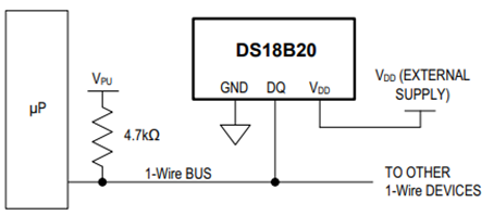
• 外付け部品不要。寄生電源モードでは2 ピン(DQとGND)のみで動作
• マルチドロップ機能により、分散型の温度検知アプリケーションを簡素化
• 各デバイスはオンボードROMに保存された固有の64-bitシリアルコードを保有
• ユーザー定義可能な不揮発(NV)アラーム設定に対応。Alarm Search Commandにより、設定範囲外の温度を検出したデバイスを識別
• パッケージ:8-Pin SO(150 mils)、8-Pin µSOP、3-Pin TO-92
このデモで使用した3つのAnalog Devicesの DS18B20 温度センサは、以下のようにTO-92 形状のものです。

Analog Devicesの DS18B20 温度センサのブロック図は以下のとおりです。

DS18B20 の中核機能は、温度センサの温度をデジタルで直接出力することです。温度センサの分解能はユーザーが9、10、11、もしくは12ビットから設定でき(コンフィギュレーションレジスタ経由)、それぞれ0.5°C、0.25°C、0.125°C、0.0625°C刻みに対応します。電源投入時のデフォルト分解能は12ビットです。 DS18B20 が出力する温度データは摂氏(°C)で校正されています。華氏(°F)で扱う場合は、ルックアップテーブルまたは変換ルーチンが必要です。温度データは、以下の表に示すように、温度レジスタに16ビットの符号拡張付き2の補数として格納されます。

必要に応じて、以下のブロック図に示すように、VDDピンに外部電源を接続する通常の方法でDS18B20 に電源を供給することもできます。
DS18B20 の内部メモリ構成は以下のとおりです。

メモリは、SRAMスクラッチパッドと、高温/低温アラームのトリガレジスタ(THとTL)およびコンフィギュレーションレジスタ用の不揮発性EEPROMストレージで構成されています。なお、DS18B20 のアラーム機能を使用しない場合、THとTLレジスタは汎用メモリとして利用できます。
バスマスターがROMコマンド(0x55)を使って通信対象の DS18B20 を指定した後、マスターは DS18B20 のFunctionコマンドを発行できます。これらのコマンドにより、DS18B20 のスクラッチパッドメモリへの書き込みと読み出し、温度変換の開始、電源モードの決定などを行うことができます。DS18B20 のFunctionコマンドは以下の表のとおりです。

このデモでは Raspberry Pico 2 W を使用し、36番ピンから 3.3Vを供給、38番ピンを「グランド」リファレンスとして利用しました。また、3つのAnalog Devicesの DS18B20 温度センサと、GPIO 15(20番ピン)に 3.3Vのプルアップ抵抗を接続し、これを1-Wireデータバスとして使用しています。

これらの DS18B20 デバイスが同時に利用できることを示すために、1-Wireバス上に 3つのAnalog Devicesの DS18B20 温度センサを配置しました。Raspberry Pico 2 W 側では、内部PIOのステートマシンonewire_library.pioを用いて、カスタムの1-Wire通信プロトコルインターフェースを実装し、C SDKを利用したCアプリケーションからアクセスしました。以下は、このデモで使用したonewire_library.pioのPIOステートマシン定義ファイルです。
;
; Copyright (c) 2023 mjcross
;
; SPDX-License-Identifier: BSD-3-Clause
;

; Implements a Maxim 1-Wire bus with a GPIO pin.
;
; Place data words to be transmitted in the TX FIFO and read the results from the
; RX FIFO. To reset the bus execute a jump to 'reset_bus' using the opcode from
; the provided function.
;
; At 1us per cycle as initialised below the timings are those recommended by:
; https://www.analog.jp/ja/technical-articles/1wire-communication-through-software.html
;
; Notes:
;   (1) The code will stall with the bus in a safe state if the FIFOs are empty/full.
;   (2) The bus must be pulled up with an external pull-up resistor of about 4k.
;       The internal GPIO resistors are too high (~50k) to work reliably for this.
;   (3) Do not connect the GPIO pin directly to a bus powered at more than 3.3V.

.program onewire
.side_set 1 pindirs

PUBLIC reset_bus:
        set x, 28       side 1  [15]    ; pull bus low                          16
loop_a: jmp x-- loop_a  side 1  [15]    ;                                  29 x 16
        set x, 8        side 0  [6]     ; release bus                            7
loop_b: jmp x-- loop_b  side 0  [6]     ;                                    9 x 7

        mov isr, pins   side 0          ; read all pins to ISR (avoids autopush) 1
        push            side 0          ; push result manually                   1
        set x, 24       side 0  [7]     ;                                        8
loop_c: jmp x-- loop_c  side 0  [15]    ;                                  25 x 16

.wrap_target
PUBLIC fetch_bit:
        out x, 1        side 0          ; shift next bit from OSR (autopull)     1
        jmp !x  send_0  side 1  [5]     ; pull bus low, branch if sending '0'    6

send_1: ; send a '1' bit
        set x, 2        side 0  [8]     ; release bus, wait for slave response   9
        in pins, 1      side 0  [4]     ; read bus, shift bit to ISR (autopush)  5
loop_e: jmp x-- loop_e  side 0  [15]    ;                                   3 x 16
        jmp fetch_bit   side 0          ;                                        1

send_0: ; send a '0' bit
        set x, 2        side 1  [5]     ; continue pulling bus low               6
loop_d: jmp x-- loop_d  side 1  [15]    ;                                   3 x 16
        in null, 1      side 0  [8]     ; release bus, shift 0 to ISR (autopush) 9
.wrap
;; (17 instructions)


% c-sdk {
static inline void onewire_sm_init (PIO pio, uint sm, uint offset, uint pin_num, uint bits_per_word) {

    // create a new state machine configuration
    pio_sm_config c = onewire_program_get_default_config (offset);

    // Input Shift Register configuration settings
    sm_config_set_in_shift (
        &c,
        true,           // shift direction: right
        true,           // autopush: enabled
        bits_per_word   // autopush threshold
    );

    // Output Shift Register configuration settings
    sm_config_set_out_shift (
        &c,
        true,           // shift direction: right
        true,           // autopull: enabled
        bits_per_word   // autopull threshold
    );

    // configure the input and sideset pin groups to start at `pin_num`
    sm_config_set_in_pins (&c, pin_num);
    sm_config_set_sideset_pins (&c, pin_num);

    // configure the clock divider for 1 usec per instruction
    float div = clock_get_hz (clk_sys) * 1e-6;
    sm_config_set_clkdiv (&c, div);

    // apply the configuration and initialise the program counter
    pio_sm_init (pio, sm, offset + onewire_offset_fetch_bit, &c);

    // enable the state machine
    pio_sm_set_enabled (pio, sm, true);
}

static inline uint onewire_reset_instr (uint offset) {
    // encode a "jmp reset_bus side 0" instruction for the state machine
    return pio_encode_jmp (offset + onewire_offset_reset_bus) | pio_encode_sideset (1, 0);
}
%}
main.cアプリケーションは次のとおりです。
/**
 * Copyright (c) 2023 mjcross
 *
 * SPDX-License-Identifier: BSD-3-Clause
**/

#include <stdio.h>
#include "pico/stdlib.h"
#include "pico/binary_info.h"

#include "onewire_library.h"    // onewire library functions
#include "ow_rom.h"             // onewire ROM command codes
#include "ds18b20.h"            // ds18b20 function codes

// Demonstrates the PIO onewire driver by taking readings from a set of
// ds18b20 1-wire temperature sensors.

int main() {
    stdio_init_all();

    PIO pio = pio0;
    uint gpio = 15;

    OW ow;
    uint offset;
    // add the program to the PIO shared address space
    if (pio_can_add_program (pio, &onewire_program)) {
        offset = pio_add_program (pio, &onewire_program);

        // claim a state machine and initialise a driver instance
        if (ow_init (&ow, pio, offset, gpio)) {

            // find and display 64-bit device addresses
            int maxdevs = 10;
            uint64_t romcode[maxdevs];
            int num_devs = ow_romsearch (&ow, romcode, maxdevs, OW_SEARCH_ROM);

            printf("Found %d devices\n", num_devs);
            for (int i = 0; i < num_devs; i += 1) {
                printf("\t%d: 0x%llx\n", i, romcode[i]);
            }
            putchar ('\n');

            while (num_devs > 0) {
                // start temperature conversion in parallel on all devices
                // (see ds18b20 datasheet)
                ow_reset (&ow);
                ow_send (&ow, OW_SKIP_ROM);
                ow_send (&ow, DS18B20_CONVERT_T);

                // wait for the conversions to finish
                while (ow_read(&ow) == 0);

                // read the result from each device
                for (int i = 0; i < num_devs; i += 1) {
                    ow_reset (&ow);
                    ow_send (&ow, OW_MATCH_ROM);
                    for (int b = 0; b < 64; b += 8) {
                        ow_send (&ow, romcode[i] >> b);
                    }
                    ow_send (&ow, DS18B20_READ_SCRATCHPAD);
                    int16_t temp = 0;
                    temp = ow_read (&ow) | (ow_read (&ow) << 8);
                    printf ("\t%d: %f C", i, temp / 16.0);

                    //Convert from C to F (Simple conversion for test purposes only)
                    float K1 = 1.8;
                    float K2 = 32.0;
                    float temp_F = temp*K1/16.0 + K2;
                    printf ("\t%d: %f F", i, temp_F);

                }
                putchar ('\n');
            }

        } else {
            puts ("could not initialise the driver");
        }
    } else {
        puts ("could not add the program");
    }

    while(true);
}
プログラムは以下のようにコンパイルされ、Raspberry Pico 2 W に書き込まれました。
DigiKey_Coffee_Cup # make -j8
DigiKey_Coffee_Cup # picotool load pio_onewire.uf2
minicomターミナルを使用して、3つのAnalog Devicesの DS18B20 温度センサから摂氏単位で温度の読み取り値を監視しました。
DigiKey_Coffee_Cup # minicom -D /dev/ttyACM0
以前このリンクでセットアップしたSparkfunのロジックアナライザを使用し、以下のように1-Wireプロトコルを観測しました。Raspberry Pico 2 W を再起動した後、3つのAnalog Devicesの DS18B20 温度センサを一定周期でポーリングした結果は以下のとおりです。

3つのAnalog Devicesの DS18B20 温度センサそれぞれの64ビットレーザーROMコードは、minicomターミナルおよび上記のSparkfunのロジックアナライザのキャプチャの両方で確認できました。以前このリンクでセットアップしたSparkFunのロジックアナライザによる以下のスクリーンショットは、1-Wireネットワーク層に類似の内蔵Analog Devicesの DS28EA00 温度センサプロトコルデコーダ、Reset/Presence検出プロセス、ROMコマンド(0x55)の拡大表示を示しています(64 ビットROMコードシーケンスに完全に一致するスレーブのみがマスターによって発行されたFunctionコマンドに応答し、バス上の他のすべてのスレーブはリセットパルスを待機します)。また、同一 1-Wireバスを共有する 3つのAnalog Devicesの DS18B20 温度センサのうち、最初に問い合わせたセンサからの応答を以下に示します。

Sparkfunのロジックアナライザには、1-Wire(リンク層)、1-Wire(ネットワーク層)の解析機能があり、このデモでは上記のように 類似のAnalog Devicesの DS28EA00 温度センサプロトコルデコーダを使用しました。Sparkfun Logicのロジックアナライザは、必要に応じて設計、テスト、およびトラブルシューティングを進めるうえで有用です。
このデモでは、C SDKを用いて Raspberry Pico 2 W から1-Wireライン上に3つのAnalog Devicesの DS18B20 温度センサを接続する方法を示しました。DS18B20 温度センサは、システム内の制御配線本数に制約がある分散型温度検知設計に適した選択肢です。寄生電源モードでは2ピン(DQとGND)だけで動作するため、マルチドロップ能力を備えた分散型温度計測アプリケーションを簡素化できます。この汎用性の高いAnalog Devicesの DS18B20 温度センサはDigiKeyから入手可能です。
同様の特性を持つ温度センサとして、Analog Devicesの DS28EA00 温度センサがあります。
このセンサは、ヒステリシスとグリッチフィルタを備えた改良版1-Wireインターフェースに加え、2つの汎用プログラマブルIO(PIO)ピン、さらにネットワーク内でデバイスの物理的な並び順を検出するためのチェーン状態遷移機能を備えています。Analog Devicesの DS28EA00 温度センサもDigiKeyから入手可能です。どうぞ良い一日を!
Este artículo está disponible en español aquí.
この記事のスペイン語版はこちらにあります。