Code Downloads
PS/2 Mouse Interface (top-level file): ps2_mouse.vhd (10.8 KB)
PS/2 Host Transceiver (must also be included in the project): ps2_transceiver.vhd (11.2 KB)
Debounce Logic (must also be included in the project): debounce.vhd (2.4 KB)
Features
- VHDL source code of a PS/2 mouse interface
- Configures a PS/2 mouse to continuously stream data
- Receives and outputs the PS/2 data over a parallel interface
- Flags when new received data is available
- Configurable system clock frequency
- Synchronizes between PS/2 and system clock domains
- Debounces incoming PS/2 signals
Introduction
This details a PS/2 mouse interface component for use in CPLDs and FPGAs, written in VHDL. The component initializes the mouse and configures it to a standard streaming data mode. From there, the component continuously receives streamed data from the mouse and outputs it to user logic over a parallel interface. A flag notifies the user logic when new data is available. This component was designed using Quartus II, version 13.1. Figure 1 illustrates a typical example of the PS/2 mouse interface integrated into a system.

Figure 1. Example Implementation
Background
PS/2 Communication
PS/2 (IBM Personal System/2) is an interface for keyboards and mice to PC compatible computer systems via a 6-pin Mini-DIN connector. The computing system must provide the keyboard or mouse with 5V source and ground connections. Communication occurs over a 2-wire serial interface, consisting of a clock line and a data line. Both lines require pull-up resistors (2kΩ shown in Figure 1). The 120Ω series resistors in Figure 1 are required to interface the 3.3V FPGA I/O to the 5V signals.
Figure 2 illustrates the receive transaction format. Both clock and data signals are logic level high when inactive (note pull-up resistors). The device provides both the clock and data. The clock has a frequency between 10 kHz and 16.7 kHz (i.e. a 60-100us period). The data begins with a start bit (logic low), followed by one byte of data, a parity bit, and finally a stop bit (logic high). The data is sent LSB first. Each bit should be read on the falling edge of the clock signal. Once complete, both the clock and data signals return to logic level high.

Figure 2. PS/2 Receive Timing Diagram
Figure 3 shows the transmit transaction format. The host first requests to transmit data by pulling the clock line low for 100us. This inhibits the PS/2 bus. Following this 100us inhibit, the host releases the clock and outputs a low start bit on the data line. The device then begins generating clock pulses. On each falling edge, the host shifts out the data bits, LSB first, followed by the parity bit. On the next clock, the host releases the data line, which is pulled high by its pull-up resistor to signal a stop bit. Having read each of these signals on the rising clock edges, the device issues a logic low acknowledge bit to communicate back to the host that it has received the data. The host reads this acknowledge bit on the last falling edge, and the device proceeds to release both the clock and data lines, which return to logic level high.

Figure 3. PS/2 Transmit Timing Diagram
PS/2 Mouse Data Format
The mouse sends data in 3-byte packets, as shown in Table 1. The first byte contains flags for X and Y overflow, the MSBs (sign bits) of the 9-bit 2’s compliment movement data, and the mouse button press data. The second and third bytes contain the lower 8 bits of the X and Y movement data, respectively. Each X and Y movement value is the change in position from the mouse’s location when the last data packet was sent.
Table 1. PS/2 Mouse Data Packet Format

Theory of Operation
PS/2 Transactions
The PS/2 Mouse Interface component uses the PS/2 Host Transceiver component documented here to perform the PS/2 transactions with the mouse.
Configuring the Mouse to Stream Data
Upon power-up or when reset, the component sends a reset command (0xFF) to the mouse. The component verifies that the mouse returns the proper acknowledge (0xFA) or else resends the reset command. The mouse then performs a self-diagnostic BAT (Basic Assurance Test). When finished, it sends the completion code (0xAA) or an error code (0xFC). The component verifies that it received 0xAA or else tries resetting the mouse again. Following the BAT code, the mouse sends its device ID (0x00), identifying itself as a standard PS/2 mouse. The component also verifies this code or resets on error.
After sending its ID, the mouse automatically enters a streaming mode, where it continuously samples and gathers data about mouse activity. However, it does not communicate this information, because data reporting is disabled by default. At this point, the component sends an enable data reporting command (0xF4). The component verifies that the mouse sends the proper acknowledge response (0xFA) or else resets. Once it receives the acknowledge, it enters a steaming state, where it continually collects mouse data as it comes in and presents it to the user logic.
The flow chart in Figure 4 illustrates this initialization process.

Figure 4. Mouse Initialization
Port Descriptions
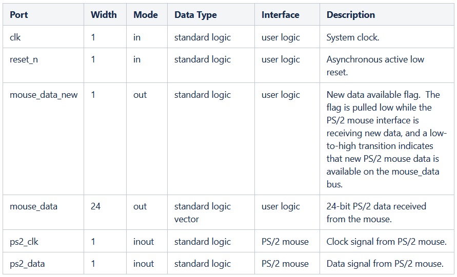
Table 2 describes the PS/2 mouse interface’s ports.
Table 2. Port Descriptions
Setting the Timing Parameters
The system clock speed affects the timing operations of the PS/2 mouse interface component. The two GENERIC parameters declared in the ENTITY, clk_freq and debounce_counter_size must be set appropriately for the component to operate correctly. The clk_freq parameter must be set to the system clock clk frequency in Hz. The default setting in the provided code is 50 MHz (the frequency at which the component was simulated and tested). The debounce_counter_size parameter must be set such that 2^debounce_counter_size / clk_freq = 5us. For a 50 MHz system clock, debounce_counter_size = 8.
The User Logic Interface
Since the PS/2 Mouse Interface component handles the mouse initialization and all PS/2 transactions, the user logic need only read new mouse data from the device. Figure 5 illustrates the interface. When the component receives the first new data byte from the mouse, it deasserts the mouse_data_new flag to indicate that a new data reception is in progress. Once it has received the complete data packet, the component presents it on the mouse_data port and asserts the mouse_data_new flag to indicate to the user logic that new mouse information is available.

Figure 5. User Logic Interface
The mouse data is mapped to the mouse_data port as shown in Table 3. See the above section on PS/2 Mouse Data Format for a more thorough description of the data.
Table 3. Data Map of mouse_data Port
Reset
The reset_n input port must have a logic high for the PS/2 Mouse Interface component to operate. A low signal on this port asynchronously resets the component. During reset, the component clears the mouse_data output port and the mouse_data_new flag. It then resets and re-initializes the PS/2 mouse.
Conclusion
This PS/2 Mouse Interface is a programmable logic component that seamlessly makes PS/2 mouse data available to FPGA logic. It synchronizes the clocks domains, debounces the input signals, resets and initializes the mouse to stream data, continuously receives the data, and notifies the user logic when new data from the mouse is available on its parallel output bus.
Related Topics
PS/2 Host Transceiver (VHDL)
PS/2 Keyboard Interface (VHDL)
PS/2 Keyboard to ASCII Converter (VHDL)
Debounce Logic Circuit (with VHDL example)