Code Downloads
Keypad Pmod Controller (top-level file): pmod_keypad.vhd (11.7 KB)
Debounce Logic (must also be included in the project): debounce.vhd (3.1 KB)
Features
- VHDL source code of a streamlined interface to Digilent’s Keypad Pmod (PmodKYPD)
- Outputs which keys are pressed on a parallel interface
- Handles up to 2 simultaneous key presses
- Eliminates false positives and false negatives inherent in the keypad’s design
- Debounces key presses (with configurable debounce time)
Introduction
This details a VHDL component that handles interfacing to the Digilent’s Keypad Pmod, shown in Figure 1. Figure 2 illustrates a typical example of this Keypad Pmod Controller integrated into a system. As shown, the Keypad Pmod Controller connects directly to the Keypad Pmod through the FPGA’s IO ports. It repetitively stimulates the keypad’s columns and reads the rows to detect key presses and then outputs the results on a 16-bit parallel interface. This component was designed using Quartus Prime 17.0.0 Lite Edition.

Figure 1. Digilent Keypad Pmod
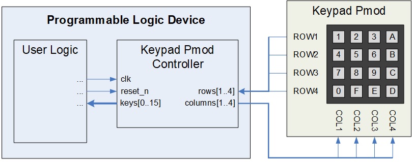
Figure 2. Example Implementation
Theory of Operation
The Keypad Pmod has a row/column matrix circuit to reduce the number of IO required to use it. Figure 3 shows the schematic of the Pmod’s relevant circuitry (except Digilent labeled the switch names in row 4 incorrectly).

Figure 3. Keypad Pmod Circuit
Detecting Single Key Presses
With no keys pressed, the row outputs are pulled up to a logic high through the 10 kΩ resistors. A single key press forms a voltage divider between the row’s 10 kΩ resistor and the connected column’s 470 Ω resistor. If the column is pulled low by the FPGA, then the row output drops below the logic low threshold voltage and is read by the FPGA as a ‘0’. Single key presses are reliably detected by reading the rows while pulling the columns low one at a time to determine which key in the row is pressed.
This approach reliably detects that a particular key was pressed if only one key was pressed.
However, additional steps still need to be taken to eliminate both false positive and false negative detections that can result if multiple keys were pressed simultaneously.
Detecting Two Simultaneous Key Presses
The single key press approach described above also detects most dual key presses but not all. It reliably detects dual key presses if only two keys are pressed and if those two keys are not in the same row.
Suppose two keys in the same row are pressed simultaneously. Since one of their columns is held high by the FPGA, that column’s 470 Ω resistor is then in parallel with the row’s 10 kΩ resistor. This changes the voltage divider circuit such that the row output is not below the logic low threshold voltage, so the FPGA input incorrectly reads that no keys are pressed (a false negative for each of the two keys).
The Keypad Pmod Controller corrects for this dual key press problem. It checks whether two keys in the same row are pressed simultaneously by pulling those two columns low at the same time. Figure 4 depicts the resulting circuit. If both keys are pressed, the row output falls below the logic low voltage threshold. Note, the row output also goes low if either of the keys is pressed alone. Therefore, Keypad Pmod Controller only accepts the result as a dual key press if neither key was independently detected by the single key press approach.

Figure 4. One Row with Two Columns Pulled Low
Eliminating False Negatives and False Positives
Three or more simultaneous key presses make the above approaches unreliable. Problems develop because resistors are usually then being connected in parallel. Many such combinations lead to either false negative or false positive results, because they drastically alter the voltage divider circuits.
After cycling through the columns and polling the rows for each single and dual key press scenario, the Keypad Pmod Controller counts the key presses detected during that polling cycle before outputting the results. If more than two keys were pressed, all results are suspect and unreliable, so no results are accepted or outputted.
In this manner, all output values are definite, reliable key presses. If more than two keys are pressed simultaneously, they are all ignored as operator error, since it is then impossible to reliably determine which keys are pressed or which are not.
Detect Time
The Keypad Pmod Controller also calculates the number of input clock cycles needed for each polling check. Once a column is pulled low, a row with a key press has an appreciable time constant before that input reaches the logic low threshold. To meet this requirement, the Controller waits 300 ns before reading the values.
The Controller performs this function using the GENERIC parameter clk_freq, which must be set to the frequency of the system clock input clk.
Debounce
Once the polling cycle completes and the detected key presses are counted to verify their legitimacy, the Controller debounces the results before outputting them. The GENERIC parameter stable_time specifies how many milliseconds a key value must remain stable before being counted as a single press.
The debounce component described here performs this function.
Configuring the Controller
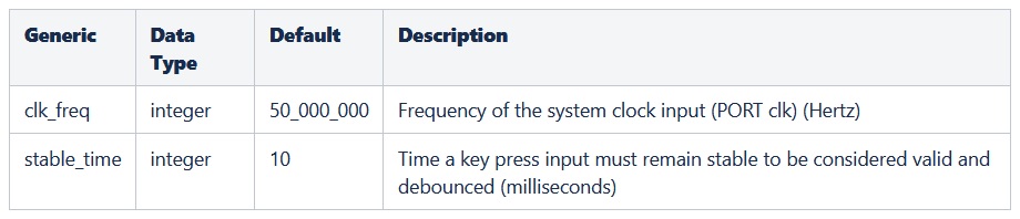
The Keypad Pmod Controller is configured by setting the GENERIC parameters in the ENTITY. Table 1 describes the parameters.
Table 1. Generic Parameter Descriptions
Port Descriptions
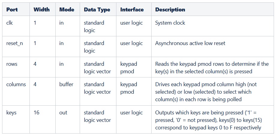
Table 2 describes the Keypad Pmod Controller’s ports.
Table 2. Port Descriptions
Connections
This Pmod has one 12-pin connector. Table 3 provides the pinout. The Keypad Pmod Controller’s ports need to be assigned to the FPGA pins that are routed to these connectors as listed.
Table 3. Keypad Pmod Pinout and Connections to Keypad Pmod Controller

Reset
The reset_n input port must have a logic high for the Keypad Pmod Controller component to operate. A low logic level on this port asynchronously resets the component. During reset, the component sets the columns outputs high, clears the keys outputs and clears all relevant internal registers. Once released from reset, the Keypad Pmod Controller resumes operation.
Conclusion
This Keypad Pmod Controller is a programmable logic component that interfaces to Digilent’s Keypad Pmod. It handles all processes necessary to reliably detect and debounce up to 2 simultaneous key presses and output the results on a parallel interface. The Controller also determines if more than 2 keys are simultaneously pressed and outputs all zeros in this case to indicate that no definite, reliable key presses can be determined, thereby eliminating the false positives and false negatives inherent in the keypad design.