We use cookies to provide our visitors with an optimal site experience. View our privacy notice and cookie notice to learn more about how we use cookies and how to manage your settings. By proceeding on our website you consent to the use of cookies.
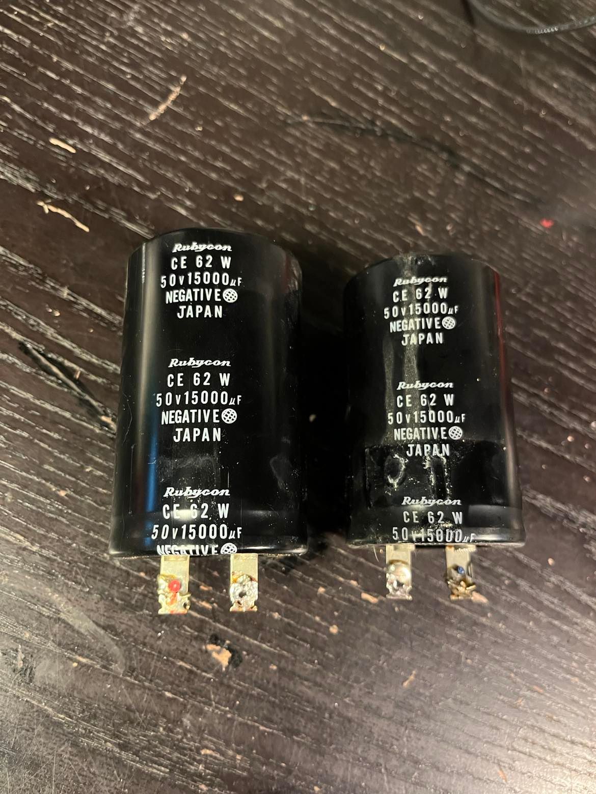
I have 2 filter caps to replace in a Fisher RS-1050. The caps are labeled CE 62 W. They are 50v, 15000mf.
I have purchased from Digi-Key and installed these : DCMC193U075BB2B. After installing, the receiver slow blow fuse blew, so I am concerned that I didn’t purchase a proper replacement.
Hi,
Welcome to the Digikey tech forum. Part DCMC193U075BB2B does not meet the same specifications as the part you are replacing. Can you send a photo of the capacitor with the markings visible to help us ID the part? You can also look at these capacitors which are 15000uF (microfarad), 50 volts as possible alternates. You will want to verify the pin spacing and body dimensions to be sure one of these will fit.
The capacitor you used is only about 27% higher in capacitance than the original, and most capacitors in the size/voltage range are +/-20% devices. Generally most linear power supply designs of the 1970’s would have slightly improved performance by increasing the filter capacitance by up to 100% without any bad side effects.
It is possible the extra capacitance is extending the charge time enough to cause the slow blow fuse to open. However I have a bad feeling you’re going to find there are more problems with the circuit than just a worn out capacitor.
To test I’d disconnect the power supply completely and use a lab supply with current limiting to check that the rest of the circuitry is not drawing too much current for the fuse.
Remove the three other fuses that are on the transformer secondary and see if the main 5A fuse still blows. If not replace the two 1A secondary fuses and test, then replace the 4A fuse and retest (could be a simple as bad light bulbs in the 4A illumination array).
There’s also a repair manual at that internet link that I haven’t read, it may have better troubleshooting tips.
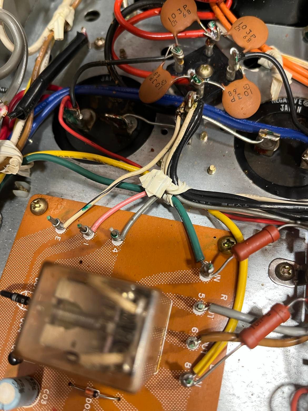
First pic above shows the original caps as wired.
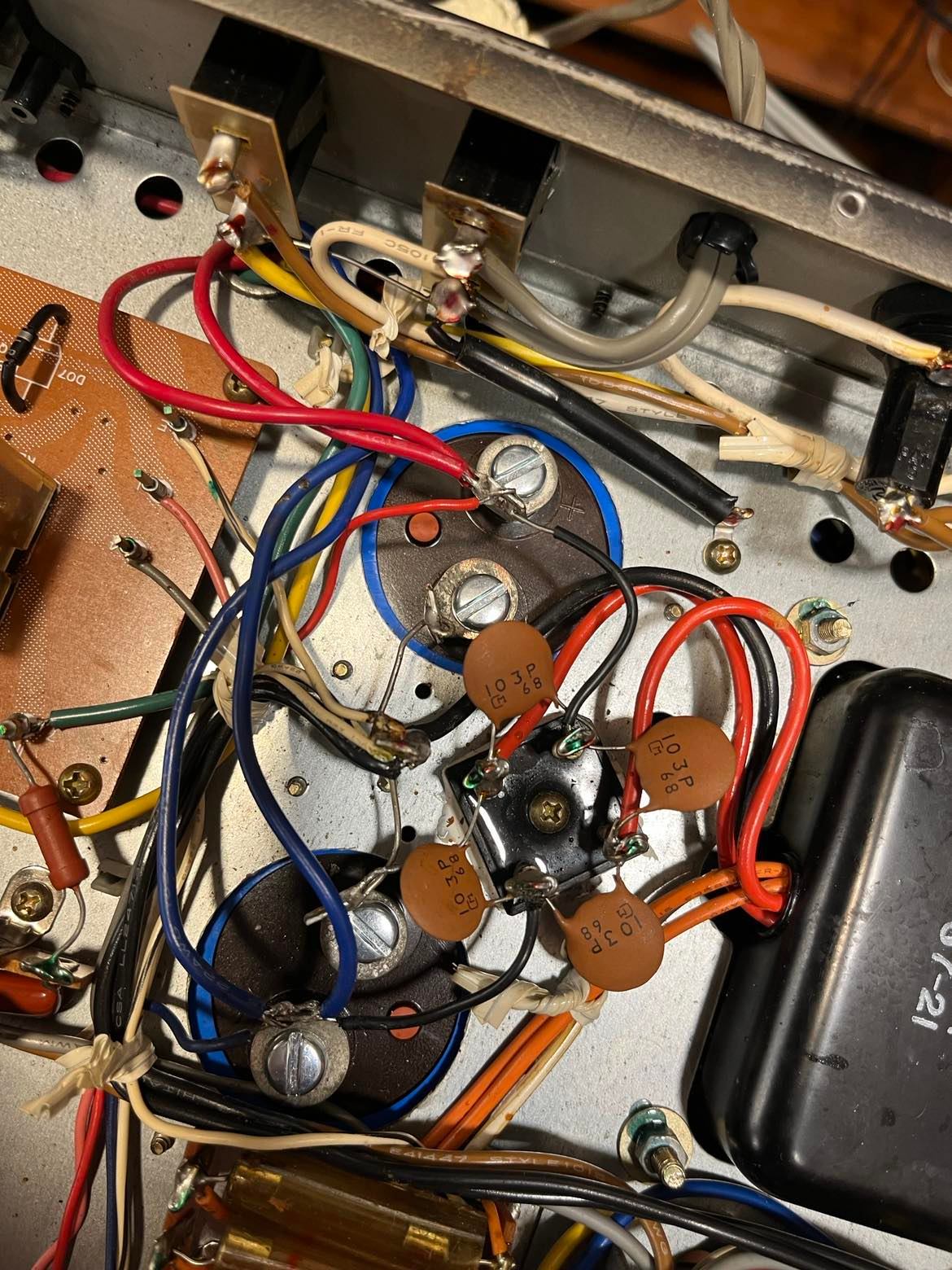
Second pic shows new caps soldered in place.
Third pic shows original caps.
I was a bit confused by the word Negative on the original caps, it didn’t seem to align with a post at all. For my new caps, I put the positive posts on the outsides, and the negatives next to each other. This in itself may be wrong.
As far as the unit itself, I did also replace two indicator lamps with LEDs, though I have ordered some original type lamps and intend to put them in . The receiver worked well in all areas except for some intermittent garbled sound in the left channel. That coupled with what looked like some fluid residue from on filter cap led me to replace them.
That’s almost certainly incorrect, and if the fuses weren’t blowing one or both caps probably would be in short order, since they do not tolerate reverse voltage gracefully. The bridge rectifier (black square) should have + and - marks somewhere; use those marks to figure out which way the series-connected caps should be connected.
Thank you all so much. I love this hobby, but I am self-teaching along the way, and that was a valuable lesson to learn about how the capacitors are in series, and how to see that represented in the schematic. I ended up rotating one cap 180 degrees, and after starting it up with the variac and the dim bulb tester it was stable. Right now I am listening to a CD through it, and the garbled sound is gone!. I appreciate you all!