Good afternoon,
Recently I’ve purchased a CFM500S480 produced by Cincon (TW). Also on their site I had read this article ( https://www.cincon.com/newsdetail_en.php?id=15424 ) regarding the series connection of 2 CFM500S240 and I have some questions.

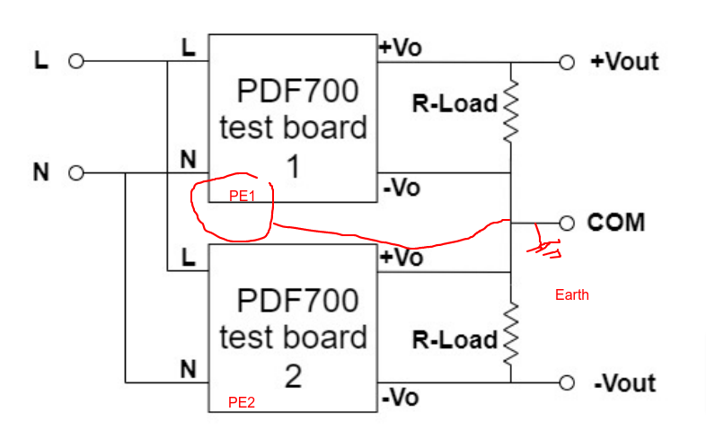
In the attached picture the two power supplies connected for series operation.
I would like to know how I can do the earthing (connecting the PE pins to the chassis of the apparatus and to the Earth ground). Also I would like to know if the +/- operation is possible → in this case to obtain a differential +/- 24V.
Many thanks in advance
Hello,
We are looking into this request and will post the answer as soon as we can get the right information.
Thank you
Ryan Urness
1 Like
It appears to me that the PE connection to the supply would be done through one of the mounting screws, since there appears to be no other connection point. Look for a label to this effect on the PCB. The outer chassis of the system would typically be connected to earth ground through the power supply cable near the power entry point.
Connecting two isolated supplies in series to create a +/- supply is permissible and quite commonplace.
Hi @rick_1976 ,
Thank you for the quick answer. I had identified the PE on the PCB since the beginnimg, that was not the point. Let’s assume the following connection:
My concern is that the PE pin is connected to -Vo on each board. Therefore by connecting both PE pins to the Earth connection as suggested in this picture I am practically shorting the +Vo and -Vo on the lower board (the negative side of the differential supply)
I think that the following connection should be ok:
Am I right?
Many thanks again for your time
This is not typically the case, since it violates the principle of an isolated supply. If for some reason that is true of the supply in question, it would not be suitable for series connections.
1 Like
Hello @rick_1976
According to theapplication note, for Cincon CFM500 series the electrical diagramm is:
I thnink that you’re righat, meaning that I can connect the 2 modules in series in order to obtain the +/-24 V differential and in the mean time to connect each PE (FG in the diagramm) to the apparatus Earth.
Next week I’ll receive the second module, I’ll do the test and let you know.
In the mean time I would like your opinion on this topology (since I posted here the electrical diagramm).
Many thanks again,
Cristian
The secondary side of most all isolated converters have a capacitive coupling to protective earth/neutral to control EMI. This does not prevent connection of such supplies in series, since no DC current flow through this capacitor occurs.
The diagram for the supply above is a simplified representation. It doesn’t indicate anything unusual or uncommon, but also doesn’t offer enough information to offer comment on the design itself.