Description
This project discusses implementing an SMS text alert capability that sends an SMS when data from a LoRaWAN sensor meets a predefined condition. The project example use case monitors the time an AC load is in the ON state and sends an SMS when the time exceeds a specified value. To implement this capability, Machinechat’s JEDI Rule Engine is configured to trigger sending of an email when the load being monitored is ON for a length of time equal to or exceeding a predefined limit. The SMS text alert occurs from the JEDI email sent to a mobile carrier’s “email to text” application platform ( i.e. - phone#@vtext.com for Verizon). Information on setting up JEDI email and text(SMS) notifications can found at Configuring JEDI One to send email and text (SMS) notifications.

Hardware
- Seeed reServer
reServer is based on an ODYSSEY X86 v2 board and powered by Intel® Core™ 11th Gen. i3 and Intel UHD Graphics 48EUs - Seeed SenseCAP Outdoor Gateway - LoRaWAN US915MHz
SenseCAP LoRaWAN Gateway is based on LoRaWAN® protocol, applicable for low-power, long-distance environmental data collection and monitoring. - Seeed Grove LoRa-E5 board
STM32WLE5JC, SX126x LoRa RF Grove Platform Evaluation Expansion Board - Seeed Seeeduino Xiao board
SAMD21G18 Seeeduino XIAO series ARM® Cortex®-M0 MCU 32-Bit Embedded Evaluation Board - Seeed Seeeduino Xiao Grove Shield
Grove Shield Base for XIAO - with embedded battery management chip - DFRobot SEN0287 Gravity AC Current Sensor
5 Amp AC Current Sensor.
Software
- JEDI Pro or JEDI Pro SSE
Adaptable software for IoT data collection, visualization, monitoring and data storage that can be integrated into IoT solutions. Capabilities include: collect data from sensors, devices and machines; build intuitive real-time and historical data and system view dashboards; create rules to monitor and respond to data conditions automatically; receive alert notifications by email and SMS. JEDI Pro SSE is the Seeed Studio Edition version of JEDI Pro that adds a Data Collector for Seeed’s line of SenseCAP LoRaWAN sensors - ChirpStack
The ChirpStack open-source LoRaWAN Network Server stack provides open-source components for LoRaWAN networks. The modular architecture makes it possible to integrate within existing infrastructures. - Arduino
Arduino is an open-source electronics platform based on easy-to-use hardware and software.
Background
This post is a follow-on project that uses the same hardware as the related TechForum post Remote Wireless LoRaWAN AC Load Current Monitor using Machinechat and Chirpstack which details setting up a smart remote wireless current sensor that monitors device load current and sends current/load data over LoRa to Chirpstack and Machinechat’s JEDI IoT platform. This project modifies the Arduino code to add load on time counter data to the LoRa data payload. Additionally, Machinechat’s JEDI Rule Engine is used to trigger sending of an SMS text alert.
Implementation
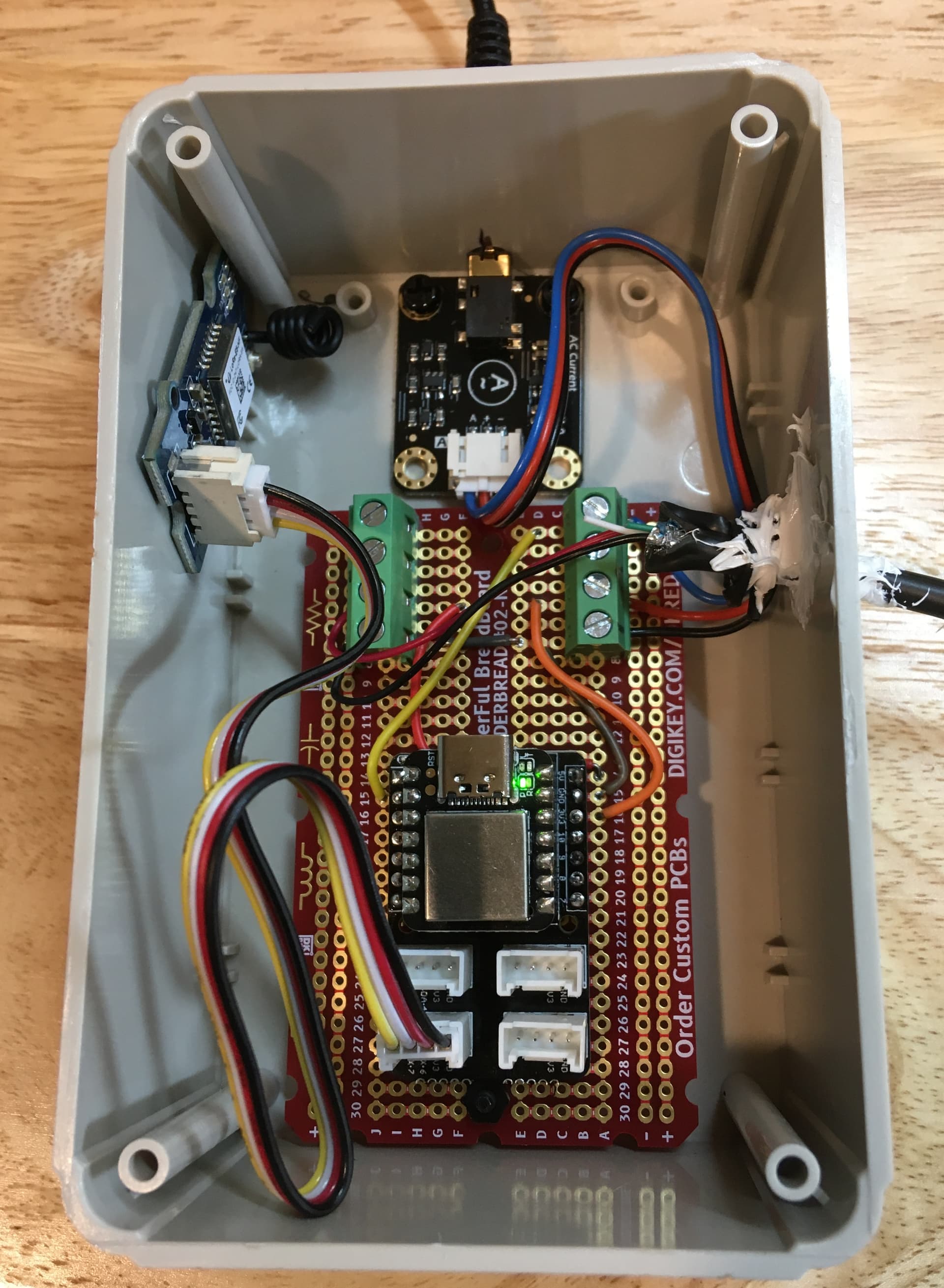
The hardware, LoRaWAN and Machinechat IoT monitoring system used in the project are the same as in the post Remote Wireless LoRaWAN AC Load Current Monitor using Machinechat and Chirpstack. An external USB 5V power supply powers the Seeeduino Xiao and the Xiao’s 3V3 output powers the Grove LoRa-E5 board and SEN0287 sensor. The Xiao UART is connected to the TX/RX pins of the Grove LoRa-E5 and Xiao input pin 1 connected to the analog output of the SEN0287 current sensor board. The SEN0287 AC current transformer is clamped around the hot wire powering the load. Below schematic diagram illustrates how the circuit is implemented (see Scheme-it Project: LoRaE5_Xiao_CurrentSensor ).

For the mechanical housing, the Xiao (attached to a Xiao Grove shield soldered to a SOLDERBREAD#02-ND proto board) and LoRa-E5 boards are mounted in an enclosure (Hammond Manufacturing part# RL6225-F) with the +5V power provided over a USB cable.
The Arduino application code runs on the Seeeduino Xiao to send AT commands to the LoRa-E5 and read analog voltage current sensor measurements on pin 1. The application joins the LoRa network, reads the SEN0287 current sensor, calculates average AC current, determines load state transitions and elapsed load “ON” time, encodes average current and load on time data in CayenneLPP format, sends the data over LoRa, delays and loops back to repeat.
Set up the Arduino code for the LoRaWAN Current Sensor
1 - Set up Arduino on the Seeeduino Xiao. See link Getting started with Seeeduino Xiao
2 - Install libraries needed for application. Add these libraries thru Arduino’s Library Manager:
3 - Code walkthrough (Xiao_LoRaE5CayenneLPP_SEN0287avgCurrentLoadOnTimeV3.ino)
Initial setup
#include <Arduino.h>
#include <CayenneLPP.h>   //library for Cayenne Low Power Payload LPP encoding for use in LoRa payload

// this version uses RunningAverage code
#include "RunningAverage.h"
RunningAverage myRA(100);
int samples = 0;

// general parameters
const int RecordTime = 3; //Define Measuring Time (Seconds)
const int ledPin =  13;      // the number of the LED pin

float currAvg;   //average current
float currMax; //max current
float currMin; //max current

// analog current sensor parameter
#define ACPin 1
#define VREF 3.3
#define ACTectionRange 5;    //set Non-invasive AC Current Sensor tection range (5A,10A,20A)

CayenneLPP lpp(51);   //setup Cayenne LPP (low power payload) buffer - per documentation 51 bytes is safe to send

static char recv_buf[512];
static bool is_exist = false;
static bool is_join = false;
static int led = 0;

int buf_size;  //Cayenne LPP buffer payload size
int Pointer;   //pointer used in Cayenne LPP buffer
int Offset = 12;    //offset to where Cayenne LPP payload data starts
int Loop1;       //loop counter in LoRa payload builder
int Loop2;       //loop counter in LoRa payload builder
int Loop3 = 0;       //loop counter in LoRa parameter send

int transition = 0;  //transition defines state 2 when load ON=>OFF, 1 when load OFF=>ON, 0 when otherwise
unsigned long int timeOn;
unsigned long int timeOff;
unsigned long int elapsedTime = 0;
unsigned long int timestamp = 0; //temporary holding value for millis() time
float onTime = 0;
int Etime = 0; // variable to store elapsed time the load has been on
byte TimeCnt = 0; //byte variable to hold value to send as byte data in LoRa CayennLPP payload


static int at_send_check_response(char *p_ack, int timeout_ms, char *p_cmd, ...)
{
    int ch;
    int num = 0;
    int index = 0;
    int startMillis = 0;
    va_list args;
    memset(recv_buf, 0, sizeof(recv_buf));
    va_start(args, p_cmd);
    Serial1.printf(p_cmd, args);
    Serial.printf(p_cmd, args);
    va_end(args);
    delay(200);
    startMillis = millis();

    if (p_ack == NULL)
    {
        return 0;
    }

    do
    {
        while (Serial1.available() > 0)
        {
            ch = Serial1.read();
            recv_buf[index++] = ch;
            Serial.print((char)ch);
            delay(2);
        }

        if (strstr(recv_buf, p_ack) != NULL)
        {
            return 1;
        }

    } while (millis() - startMillis < timeout_ms);
    return 0;
}

 // LoRa message receive message buffer RSSI and SNR
static void recv_prase(char *p_msg)
{
    if (p_msg == NULL)
    {
        return;
    }
    char *p_start = NULL;
    int data = 0;
    int rssi = 0;
    int snr = 0;

    p_start = strstr(p_msg, "RX");
    if (p_start && (1 == sscanf(p_start, "RX: \"%d\"\r\n", &data)))
    {
        Serial.println(data);
        led = !!data;
        if (led)
        {
            digitalWrite(LED_BUILTIN, LOW);
        }
        else
        {
            digitalWrite(LED_BUILTIN, HIGH);
        }
    }

    p_start = strstr(p_msg, "RSSI");
    if (p_start && (1 == sscanf(p_start, "RSSI %d,", &rssi)))
    {
         Serial.println(rssi);
    }
    p_start = strstr(p_msg, "SNR");
    if (p_start && (1 == sscanf(p_start, "SNR %d", &snr)))
    {
        Serial.println(snr);
    }
}


void setup(void)
{
    Serial.begin(9600);

    pinMode(LED_BUILTIN, OUTPUT);
    digitalWrite(LED_BUILTIN, HIGH);

    myRA.clear(); // explicitly start clean with RunningAverage by clearing buffer

    Serial1.begin(9600);                  //UART serial1 connection to LoRaE5
    Serial.print("E5 LORAWAN TEST\r\n");

    if (at_send_check_response("+AT: OK", 100, "AT\r\n"))
    {
        is_exist = true;
        //at_send_check_response("+ID: AppEui", 1000, "AT+ID\r\n");
        at_send_check_response("+MODE: LWOTAA", 1000, "AT+MODE=LWOTAA\r\n");
        //at_send_check_response("+DR: EU868", 1000, "AT+DR=EU868\r\n");  //original
        at_send_check_response("+DR: US915", 1000, "AT+DR=US915\r\n");
        //at_send_check_response("+CH: NUM", 1000, "AT+CH=NUM,0-2\r\n");  //original
        at_send_check_response("+CH: NUM", 1000, "AT+CH=NUM,8-15,65\r\n"); // configure channels to match chirpstack
        //at_send_check_response("+KEY: APPKEY", 1000, "AT+KEY=APPKEY,\"2B7E151628AED2A6ABF7158809CF4F3C\"\r\n");
        at_send_check_response("+CLASS: C", 1000, "AT+CLASS=A\r\n");
        at_send_check_response("+PORT: 8", 1000, "AT+PORT=8\r\n");
        at_send_check_response("+ID: AppEui", 1000, "AT+ID\r\n");
        at_send_check_response("+KEY: APPKEY", 1000, "AT+KEY=APPKEY,\"2B7E151628AED2A6ABF7158809CF4F3C\"\r\n");
        delay(200);
        is_join = true;
    }
    else
    {
        is_exist = false;
        Serial.print("No E5 module found.\r\n");
    }

}
Main loop - measure/sample AC current sensor and use RunningAverage library to determine average current, determine AC load state elapsed load on time and load cycle period time. Data is encoded in CayenneLPP format and sent as LoRa payload data.
void loop(void)
//void loop()
{

    // measure SEN0287 current
    float AC_current = readACCurrentValue();
    Serial.print("transition state = ");
    Serial.println(transition);
    delay(100);


    //measure();
    myRA.addValue(AC_current);
    samples++;
    delay(100 * RecordTime);
    //debug code to print out sample# and min, average, max current
    Serial.print("samples = ");
    Serial.print(samples);
    Serial.print("\t");
    Serial.print("MinAvgMax  ");
    Serial.print(myRA.getMin(), 3);
    currMin = myRA.getMin();
    Serial.print("\t");
    Serial.print(myRA.getAverage(), 3);
    currAvg = myRA.getAverage();
    Serial.print("\t");
    Serial.println(myRA.getMax(), 3);
    currMax = myRA.getMax();
    Serial.println(AC_current, 3);


    //check if load turned off
    if ((transition == 2) && (AC_current < 0.9*currAvg))
      {
       transition = 1;
       Serial.println("load turned off");
      }

    //check if load turned on
    if ((transition == 0) && (AC_current > 1.1*currAvg))
      {
        timeOn= millis();
        transition = 2;
        samples = 0;
        Serial.println("load turned on");
      }

    //print out load on time cycle period if load turned off
    if (transition == 1)
      {
        timeOff = millis();
        elapsedTime = (timeOff - timeOn)/1000;
        onTime = (elapsedTime/60 + 0.5);
        //TimeCnt = (elapsedTime/60 + 1); // minimum time is 1
        transition = 0;
        Serial.print(onTime);
        Serial.println("******* load on time in minutes ********");
        //Serial.println(TimeCnt);
        lpp.reset();
        lpp.addAnalogOutput(6, onTime);  // add load on time cycle period data to payload
        BuildPayload();
        samples = 0;  // reset samples to 0
        myRA.clear(); // clear myRA data
        // note: this starts sampling new current data again at the main loop beginning
      }


    // due to character byte limitatations in LoRa payload buffer, need to alternate (note: not used in this code)


    Serial.print("Loop3 = ");  //debug code
    Serial.println(Loop3);    //debug code

    //if ((Loop3 == 0) and (samples == 30))
    if (samples == 30)
    //when samples = 30, add average current to LoRa payload
    {
      lpp.reset();
      lpp.addAnalogOutput(5, currAvg);  //add channel 5, average current to payload
      if (transition == 2) //if load current is on, update on time and add to LoRa CayenneLPP payload
      {
        timestamp = millis();
        elapsedTime = (timestamp - timeOn)/1000;
        onTime = (elapsedTime/60 + 0.5); //float variable
        TimeCnt = (elapsedTime/60 + 1); // byte variable of load on time counter (min = 1)
        Etime = onTime;  // int variable
        Serial.print(Etime);
        Serial.print("##### timestamp load ontime in minutes ********  and as byte data ");
        Serial.println(TimeCnt);
        lpp.addDigitalOutput(1, TimeCnt);  //channel 1, add load on time counter data to payload as digital output byte

      }
      Loop3 = 1;
      BuildPayload();
    }
    else if((Loop3 == 1) and (samples == 150))
    //when samples = 150, add average current to LoRa payload
    {
      lpp.reset();
      lpp.addAnalogOutput(5, currAvg);  //channel 5, average current
      Loop3 = 0;
      // check if load is on, if on then add load on time counter data to payload
      if (transition == 2) //if load current is on, update on time and add to LoRa CayenneLPP payload
      {
        timestamp = millis();
        elapsedTime = (timestamp - timeOn)/1000;
        TimeCnt = (elapsedTime/60 + 1); // byte variable of load on time counter (min = 1)
        lpp.addDigitalOutput(1, TimeCnt);  //channel 1, add load on time counter data to payload as digital output byte
      }
      BuildPayload();
    }
    else
    {
      Serial.println("sample limits not reached");
    }

  // clear running average data after samples = 151
  if (samples == 151)
  {
    samples = 0;
    myRA.clear();
    Serial.println("RunningAverage data cleared");
  }

}
Read SEN0287 AC current sensor and related code
// routine for reading current from DFRobot code for SEN0287
float readACCurrentValue()
{
  float ACCurrentValue = 0;
  float peakVoltage = 0;
  float voltageVirtualValue = 0;  //Vrms
  for (int i = 0; i < 10; i++)
  {
    peakVoltage += analogRead(ACPin);   //read peak voltage
    delay(1);
  }
  peakVoltage = peakVoltage / 10;   //average out peak voltage
  peakVoltage = peakVoltage - 7.5; //calibrate out 0 current ADC reading (about 5mV)
  if (peakVoltage < 0.03) peakVoltage = 0; // zero out 0 current measurement

  voltageVirtualValue = peakVoltage * 0.707;    //change the peak voltage to the Virtual Value of voltage
  /*The circuit is amplified by 2 times, so it is divided by 2.*/
  voltageVirtualValue = (voltageVirtualValue / 1024 * VREF ) / 2;
  ACCurrentValue = voltageVirtualValue * ACTectionRange;

  if (ACCurrentValue < 0.09) ACCurrentValue = 0; //zero out low current reading

  return ACCurrentValue;
}
Latest source code for the Xiao_LoraE5CayenneLPP_SEN0287avgCurrentLoadOnTimeV3.ino application is on github at below link:
Determine Grove LoRa-E5 board device EUI
In order to add the sensor to a LoRaWAN network, the device EUI needs to specified. In Arduino, compile and upload Xia_LoRaE5CayenneLPP_DS18B20tempSensorRev2.ino code into Seeeduino Xiao and enable Serial Monitor. Review Serial Monitor output to determine Grove LoRa-E5 device EUI (see example below).

Add the LoRa-E5 based sensor node to the ChirpStack LoRaWAN network server
(note: this project and below steps assume that a ChirpStack based private LoRaWAN network is active and in range of the LoRa-E5 sensor node, if not refer to TechForum post Set up a private LoRaWAN Sensor Network with Machinechat and Seeed SenseCAP )
1 - In ChirpStack, select Device-profile and Create. Name Device-profile “Seeed LoRaE5”, Select “1.0.2” for LoRaWAN MAC version, Select “A” for LoRaWAN Regional Parameters version, Select “Default ADR algorithm” for ADR algorithm, and enter “3600” for Uplink interval. In JOIN(OTAA/ABP) tab, check box for “Device supports OTAA”. In CODEC tab, select “Cayenne LPP” in CODEC dropdown list. (note: creating a new profile is not needed if you have already created a device profile with these parameters, it just needs to be selected)

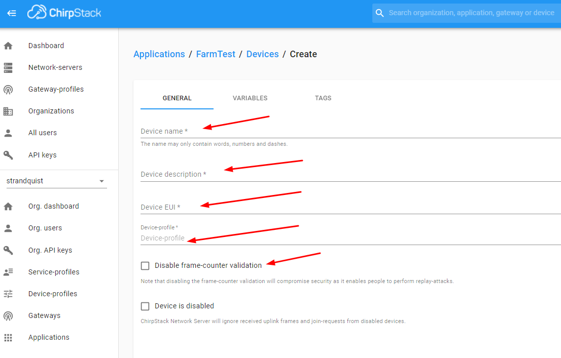
2 - In ChirpStack, select Applications, then select “FarmTest” and then select Create. Enter “XiaoLoRaSEN0287” (or whatever you prefer) for Device name, enter “description” for Device description, enter Device EUI for Grove LoRa-E5 board (determined from above step “Determine Grove LoRa-E5 board device EUI”), enter “Seeed LoRaE5” for Device-profile, and select CREATE DEVICE. (note 1: for initial testing and demonstration you may want to check Disable frame-counter validation box)
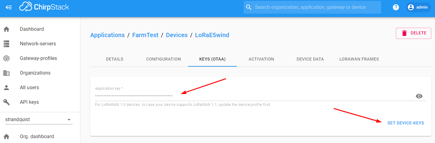
3 - Add Application key for Device. Enter Application key “2B7E151628AED2A6ABF7158809CF4F3C” (note: this is default key in LoRa-E5, to change refer to KEY section of LoRa-E5 AT Command Specification) and select SET DEVICE-KEYS.
Set up and test ChirpStack HTTP Integration with JEDI Pro Generic LoRaWAN Custom Data Collector
ChirpStack is modified to add HTTP integration for forwarding LoRaWAN meta and sensor data to a specified IP address. Machinechat’s Generic LoRaWAN Custom Data Collector Plug-in is used for listening to the specified IP address and parsing the LoRaWAN data for review (when debug enabled) and use in the JEDI Pro platform.
(note: The Custom Data Collector consists of two files, lorawan-linux.bin and config.yml that are available from Machinechat at: https://support.machinechat.io/hc/en-us/articles/6046199010327-Generic-LoRaWAN-Custom-Data-Collector-Beta-for-JEDI-PRO-Linux )
1 - Enable HTTP Integration in ChirpStack.
In “Applications”, select “FarmTest” and then “Integration” tab. Select “Add” in ChirpStack Integrations screen.
(note: if “FarmTest” HTTP Integration has already been implemented for a previous device, you can skip steps 1-4 and go directly to Step 5 to edit the config.yml file)

2 - Configure HTTP Integration
Select “JSON” for Payload marshaler , add IP address (use same IP as in config.yml file) for Endpoint URL , and select ADD INTEGRATION

3 - Copy lorawan-linux.bin and config.yml files to the ~/jedi/plugins directory where JEDI Pro is installed on the Ubuntu Linux Mini-PC. Modify config.yml file to enable debug and specify IP listening address.
(note: if you have previously installed the lorawan-linux.bin and config.yml files for a different sensor, all you need to do is edit config.yml as shown in step 5 to add the info for average current and load on time parameters)

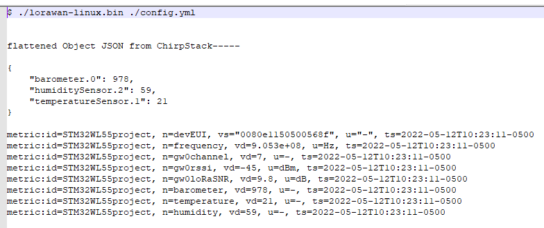
4 - Run Custom Plug-In on command line using “./lorawan-linux.bin ./config.yml” on terminal in Ubuntu Linux Mini-PC and monitor output data. Data should look similar to below (note: remember to make lorawan-linux.bin file executable):
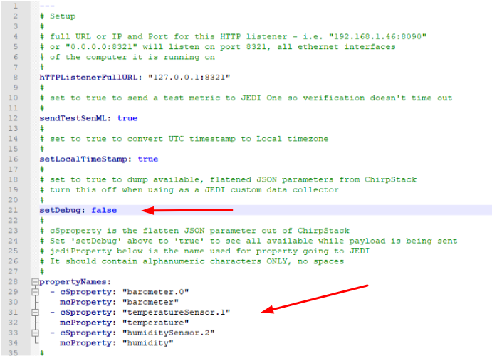
5 - Edit config.yml file to map LoRaWAN data to JEDI Pro data parameters and disable debug. For this project example, edit propertyNames so LoRaWAN cSproperty: “analogOutput.5” is mapped to mcProperty: “AvgCurrent”, cSproperty: digitalOutput.1” is mapped to mcProperty: “loadOnMinutes” , and LoRaWAN cSproperty: “analogOutput.6” is mapped to mcProperty: “loadOnTime”. Disable debugging by setting “setDebug:” to false and save file.
(note: you will need to reboot the server which is running ChirpStack for changes to take effect)
Set up JEDI Pro Custom Data Collector
In JEDI Pro, select “Settings” tab, then select “Data Collectors” and select “Add Collector”. (note: if you have previously added the LoRaWAN custom data collector to your JEDI application these steps are not necessary and you can go to “Set up JEDI Data Dashboard” step below to add charts)

Configure Collector as shown below. Name Data Collector “LoRaWAN” (or whatever you prefer), select Collector Type as “Custom Plug-In”, select “lorawan-linux.bin” as Plug-In Executable file, enter location of config.yml file (example: “/home/scottr/jedi/plugins/config.yml” for Plug-in Options, select check box for “Run As Background Process and Monitor” , then select “VALIDATE PLUG-IN” to verifiy functionality.

Set up JEDI Data Dashboards
In JEDI Pro, select “Data Dashboards”, then select “+” to add a new chart. Configure data charts for SEN0287 Average Current and Load On Time and select “Add” to include in your Data Dashboard(see example below)

Set up JEDI Rule to Trigger SMS Text Alert when Specified Condition Occurs
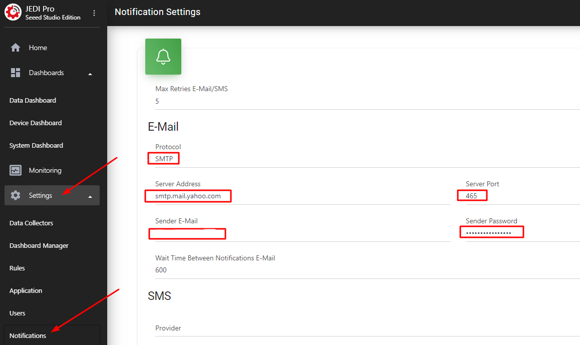
Since an email from JEDI to the mobile carrier’s email-to-text application is used to send an SMS text, email Notification needs to be set up. In JEDI, select “Settings” tab, then select “Notifications”. Once in Notifications you will need to configure the E-Mail settings for Protocol, Server Address, Server Port, Sender E-mail, and Sender Password. For this project example, Yahoo Mail is used and information on configuring the settings can be found at POP and SMTP access settings and instructions for Yahoo Mail.
The JEDI Rule Engine needs to configured to send an email for a specified condition. In “Settings” select “Rule” and click “Add Rule”.

In the Rule tab, specify “Rule Name” (i.e., LoadOnTimeExceedsLimit) and set “Rule Type” (i.e., Condition). In “Condition” select "Data Source (i.e., /XiaoLoRaSEN0287/LoadTimeCounter), select “Operators” (i.e., >=), and “Values” (i.e., Number = 5 ). Then select “+” to add an Action

In “Action”, enter “Action Name” (i.e., send email text), set “Action Type” to Notification, enter “Email List” (i.e., phone#@vtext.com for Verizon) and “SAVE”.

When the value of “loadOnMinutes” is >= 5 minutes, the email/text is sent (11:01 am CST on 2023-02-24)

SMS text is triggered by email sent to mobile carrier. Below is example of Verizon text received (on iPhone).

Conclusion
The combination of Arduino, Seeeduino Xiao, LoRa-E5 radio, and DFRobot’s SEN0287 AC current sensor provides a flexible/expandable AC load monitoring platform that provides load current, active load on time and load cycle period data wirelessly over LoRaWAN. ChirpStack’s HTTP Integration and Machinechat’s Generic LoRaWAN Custom Data Collector are then configured to bring the data into JEDI Pro for IoT data collection, visualization, monitoring and data storage. JEDI’s highly flexible Rules Engine is easily configured to provide alerts via email or SMS. The example project can be easily modified for various sensors, conditions, use cases or other scenarios as needed.
References
- Seeed - Getting Started with reServer
- Seeed - SenseCAP Outdoor Gateway - LoRaWAN US915MHz
- Seeed - Seeeduino Xiao Wiki
- Seeed - Grove - LoRa-E5 Board
- Seeed - LoRa-E5 AT Command Specification
- DFRobot - SEN0211 AC Current Sensor Wiki
- Getting Started with machinechat’s JEDI One IoT Platform
- Machinechat - Building a private, edge-based LoRaWAN IoT sensor network