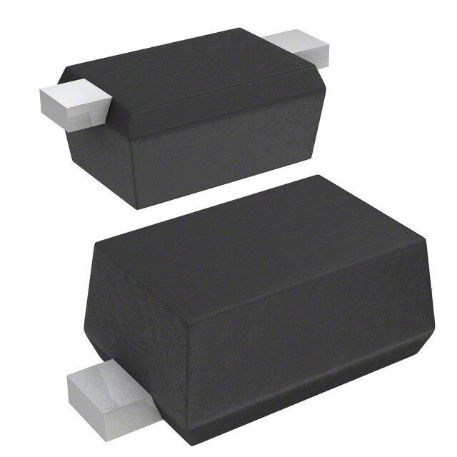
This Product Selection Guide contains information to help select products in the Variable Capacitance (Varicaps, Varactors) category on DigiKey.com
Variable capacitance diodes are produced and characterized for use as electronically-variable capacitors, and are widely used in tuning and frequency synthesis applications. While most all diodes exhibit a junction capacitance that decreases as the amount of reverse bias voltage applied increases and are capable of functioning as variable capacitance diodes, products specifically marketed as such are produced and characterized with this use in mind.
SelectionCharacteristics
Capacitance @ Vr, F: Characterizes the capacitance exhibited by a device when reverse-biased, at the indicated values of reverse voltage and test frequency.
Capacitance Ratio: Typical ratio of device capacitances measured at two specified reverse bias voltages, the choice of which often implies the bias range over which the capacitance vs. bias relationship is approximately linear.
Capacitance Ratio Condition: Indicates measurement conditions for the listed capacitance ratio. For example, “C0.1/C4” signifies a ratio measured with 0.1v and 4v of reverse bias.
Voltage - Peak Reverse (Max): The maximum voltage that should be allowed to appear across a device during normal operation. Exceeding this voltage may damage the device or other system components.
Diode Type: Describes the internal diode configuration of the device and its connections.
Q @ Vr, F: A figure of merit describing a device’s resonant qualities, and the reverse bias voltage and test signal frequency at which the given value is measured.
Operating Temperature: Recommended operating temperature, typically given in a range or as a maximum. Exceeding these temperatures may affect performance or damage the device and other system components.
Mounting Type: Indicates how the device is attached.
Package / Case: Indicates the type of protective case used on an electronic component to allow easy handling, installation, and protection. This selection was determined to be the closest industry standard applicable to the supplier device packaging. Typically it is best to check the actual dimensions from the datasheet rather than depend on this terminology when designing your circuit.
Supplier Device Package: This is what the manufacturer calls the package of this device. They are manufacturer specific. It is typically best to use the actual dimensions from the datasheets rather than to go by this terminology when designing your circuit.
ProductExamples
| MFR PART # | SMV1236-079LF |
|---|---|
| DIGIKEY PART # | 863-1135-2-ND - Tape & Reel (TR) |
| MANUFACTURER | Skyworks Solutions Inc. |
| DESCRIPTION | Varactors Single 15 V Surface Mount SC-79 |
| DATASHEET | Click Here |
| MFR PART # | MAVR-011020-14110P |
|---|---|
| DIGIKEY PART # | 1465-1782-2-ND - Tape & Reel (TR) |
| MANUFACTURER | MACOM Technology Solutions |
| DESCRIPTION | Varactors Single 22 V Surface Mount 2-FlipChip |
| DATASHEET | Click Here |
| MFR PART # | KVX2122-23-0 |
|---|---|
| DIGIKEY PART # | 150-KVX2122-23-0-ND |
| MANUFACTURER | Microchip Technology |
| DESCRIPTION | Varactors Single 22 V Surface Mount SOT-23-3 |
| DATASHEET | Click Here |
| MFR PART # | BB135,115 |
|---|---|
| DIGIKEY PART # | 568-6035-2-ND - Tape & Reel (TR) |
| MANUFACTURER | NXP USA Inc. |
| DESCRIPTION | Varactors Single 30 V Surface Mount SOD-323 |
| DATASHEET | Click Here |
SchematicSymbol

Schematic symbol courtesy of Scheme-it. Please see their website for more information and symbols.
MediaLinks
Videos
Murata LXRW Series Variable Capacitors | DigiKey Daily
Articles
The Fundamentals and Application of Zener, PIN, Schottky, and Varactor Diodes


