This article is part of a guided learning series on voltage dividers.
![]() Canonical Article: Voltage Divider Fundamentals
Canonical Article: Voltage Divider Fundamentals
![]() Learning Companion (Q&A): Explore All Questions
Learning Companion (Q&A): Explore All Questions
You are reading: Question 1
What is the equation for the voltage divider?
There are two common forms equations for the voltage divider including:
-
Simplified for two resistors
-
Generalized for three or more resistors
Solution for a Two-Resistor Network
This section presents the classic equation referenced in most textbooks. In this example, the voltage is “divided” across two resistors.
The two-resistor voltage divider equation is:
V_{R2} = V_{out} = \frac{V_{in}}{R_1 + R_2} \times R_2
The input, output, and resistor relationships are shown in Figure 1.
Figure 1: Circuit diagram for the two-resistor voltage divider.
Solution for a Three-Resistor Network
The generalized equation used to determine the voltage drop across any individual series-connected resistor is:
V_{R_X} = V_{In} \left( \frac{R_X}{R_{total}} \right)
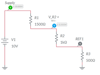
The relationship is shown in Figure 2. This example shows the voltage as measured across R2. We recognize that the multimeter’s black reference probe (REF1) is connected to the junction of R2 and R3. The multimeter’s red test probe is connected to the junction of R1 and R2.
Figure 2: A voltage divider featuring three resistors
Tech Tip: Many textbooks start by showing the two-resistor form of the equation. All students should work to generalize the equation so that it may be applied with three or more resistors. This will make subsequent lessons in AC circuits as well as nodal and mesh analysis easier to understand.
Hazards Associated with the Voltage Divider
The voltage divider is an idealized equation rarely applicable in the real world. The most common mistake is to disregard the load applied to the output of the divider. Recall that a load appears in parallel with Figure 1 R2. The result is an output voltage that is lower than expected.
You can explore the impact using DigiKey’s Voltage Divider Calculator be sure to activate the under load option as shown in Figure 3.
Figure 3: DigiKey’s calculator showing a two-resistor voltage divider under load.
Mitigation
The loading problem may be mitigated by:
-
Reducing the total resistance of the divider. With careful resistor selection (preserving the ratio of R1 to R2) the output voltage remains the same. Since the Thévenin’s equivalent resistance is lower, the output voltage will be more constant.
-
For small signals, a unity gain op amp buffer may be used.
Tech Tip: Reduced Thévenin’s equivalent resistances is undesirable as it places a larger load on the driving circuitry (Battery in Figure 3). This is an inefficient solution that can shift the loading problem from the right side of the voltage divider to the left. This is also undesirable for precision circuitry such as when a sensor with a 2 to 4 VDC output uses a voltage divider to prepare the signal for a 3.3 VDC microcontroller.
Wrapping Up
Be sure to experiment with the Digikey calculator. Try a few different resistor values and see if your hand-calculations match the calculator values.
Also, be sure to take the next critical step to understand the impact of a load resistor in parallel with R2. Add a load resistor and watch how your values change. This will be an important consideration when you reach topics such as transistor amplifiers.
![]() Article by Aaron Dahlen, LCDR USCG (Ret.), Application Engineer at DigiKey. Author bio.
Article by Aaron Dahlen, LCDR USCG (Ret.), Application Engineer at DigiKey. Author bio.


