This article is part of a guided learning series on voltage dividers.
![]() Canonical Article: Voltage Divider Fundamentals
Canonical Article: Voltage Divider Fundamentals
![]() Learning Companion (Q&A): Explore All Questions
Learning Companion (Q&A): Explore All Questions
You are reading: Question 2
Can a variable resistor be used as a voltage divider?
Closely Related Questions
This post answers the following closely related questions:
- Do potentiometers have dead zones?
- Why isn’t my potentiometer linear?
Answer
Absolutely!
In fact, the variable resistor is a common, everyday example of a voltage divider. A common application is the volume control, which allows the signal to be adjusted smoothly over a wide range.
Instead of two discrete resistors, we have a single resistor that is effectively split into two.
- The upper branch of the resistor is connected to the V_{In}
- The bottom branch is connected to ground.
- V_{Out} is taken from the variable resistor’s wiper.
Example
Suppose we set a 2 kΩ variable resistor set to its midpoint. The resulting system is shown in Figure 1 with:
- 1 kΩ as R1 and 1 kΩ as R2
- Given a 10 VDC input, we have an unloaded 5 VDC output
- The output will change in linear proportion to the position of the variable resistor ranging from 0 to 10 VDC.
Figure 1: Circuit diagram for the voltage divider. The output voltage is taken from the junction of the two resistors.
Real-World Complications
Real-world applications are considerably more complex than the simple answer suggested by the voltage divider equation. In fact, we can nearly guarantee the results will be anything but linear.
Variable Resistors are Not Linear
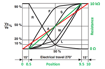
Figure 2 presents the output voltage (percentage) as a function of the variable resistor’s shaft rotation.
- The ideal linear resistor is shown as the red line.
- The green line presents the response of a Vishay P11S series potentiometer.
There is a significant difference between the ideal and the real-world performance especially when we consider the end travel, where we see a 15-degree deadband. This observed non-linear relationship for a “linear” (linear-taper) variable resistor is a stumbling point for the uninitiated.
Figure 2: The green line presents the actual response of the linear potentiometer while the red line shows our erroneous full-range assumption.
Loading Distorts a Variable Resistor’s Linearity
In the previous question, we observe deviation between the expected (incorrectly assumed) output and the actual output. This was attributed to a load being attached to the output of the voltage divider.
Unfortunately, the loading problem is nonlinear across the potentiometer’s range. A full explanation is provided in the following pair of articles. The problem is introduced in part 1 and a solution is presented in part 2. Both articles rely on an understanding of Thévenin equivalent circuits and the ability to describe the output impedance as a function of shaft rotation.
- The Curious Case of PLC Potentiometer Linearity: (Part 1) Getting Started
- The Curious Case of PLC Potentiometer Linearity: (Part 2) Lookup Table Solutions
As a preview consider the results shown in Figure 3. Here we see that error in a nonlinear function of shaft rotation. Hint: The Thévenin resistance is zero at both ends of the resistor’s travel.
Figure 3: Voltage error as a function of potentiometer rotational position
Tech Tip: The loading problem (central theme of this post) extends to filters. This article show how the amplitude and frequency response shift when a load is applied to the filter.
Wrapping Up
The potentiometer is a good example of a variable voltage divider. Perhaps the greatest utility is to demonstrate the nonlinear impact of voltage divider loading.
With regard to the variable resistor, the best use is to demonstrate where theory breaks and real engineering work begins.
This post drops the shining pebbles to guide you from the sweet comfort of theory to the messy real world with meaningful applications of core EE-101 theory.
![]() Article by Aaron Dahlen, LCDR USCG (Ret.), Application Engineer at DigiKey. Author bio.
Article by Aaron Dahlen, LCDR USCG (Ret.), Application Engineer at DigiKey. Author bio.


