Description
This post builds on an earlier post Getting Started with Advantech’s WISE-4610 Industrial LoRaWAN I/O and details using the RS-485 communication capability of the WISE-4610 to connect a Modbus RS-485 sensor and send Modbus commands to read the sensor. The WISE-4610 is added to a private TTN LoRaWAN network MQTT used to send the sensor data to Machinechat JEDI for visualization. A Seeed S-TH-01 RS-485 temperature / humidity sensor is used to demonstrate the RS-485 communication.

Hardware
- Advantech WISE-4610P-NA
Advanced Industrial LoRa/LoRaWAN Wireless I/O Module - Advantech WISE-S617T-A
Modular IoT I/O module to pair with WISE-4600 series, includes 2AI/2DI/1DO and 1RS-485 - Seeed 101990881
Product Model: S-TH-01, RS485-Industrial-grade air temperature and humidity sensor - AC/DC DIN Rail Power Supply 24VDC 36W Output
Software
- Advantech WISE Studio
WISE-Studio is a tool for configuring WISE modules. The software provides a web based interface that is similar for different models. For WISE modules configured via Ethernet, LAN, or WLAN, WISE-Studio enables communication with the WISE module’s internal web server. For modules configured via USB, WISE-Studio executes a web server on the computer installed with the software. The web server then uses the USB interface to communicate with the WISE module. - The Things Stack
The Things Stack is an enterprise grade LoRaWAN network server, built on an open source core. The Things Stack allows you to build and manage LoRaWAN networks on your own hardware or in the cloud. - JEDI Pro or JEDI Pro SSE
Adaptable software for IoT data collection, visualization, monitoring and data storage that can be integrated into IoT solutions. Capabilities include: collect data from sensors, devices and machines; build intuitive real-time and historical data and system view dashboards; create rules to monitor and respond to data conditions automatically; receive alert notifications by email and SMS. JEDI Pro SSE is the Seeed Studio Edition version of JEDI Pro that adds a Data Collector for Seeed’s line of SenseCAP LoRaWAN sensors - Modbus
The Modbus Organization is a group of independent users and suppliers of automation devices that seeks to drive the adoption of the Modbus communication protocol suite and the evolution to address architectures for distributed automation systems across multiple market segments.
Background
Advantech’s WISE-4610 has multiple I/O options in the form of plugin modules that are attached to the base of the 4610. I/O options include analog input (current or voltage), digital input/output, RS-485 and switched output voltage. Hardware used in the project include the WISE-4610P-NA and WISE-S617T modules.

The S617T includes 2 analog inputs, 2 digital inputs, 1 digital output, 2 power outputs with 1 RS-485 for I/O. The analog inputs can be configured as either voltage or current depending on jumper CN6 and CN7 setting (default setting is voltage on AI1 and AI2 inputs).The S617T nodule is inserted into the base of the WISE-4610 and secured using the provided screws. Details on pinout and I/O are shown in below I/O screw terminal connector picture and diagram.

Seeed S-TH-1 RS485 Temperature/Humidity Sensor
The S-TH-01 module provides industrial-grade sensing and compact air temperature and humidity sensing in one small-size sensor. The S-TH-1 is powered by a 3.6-30V DC supply and communication is over RS485 following Modbus protocol.
Testing RS485 Sensor Communication
It is always a good practice to test the RS485 communication with sensor being used. This is accomplished by using RealTerm serial terminal running on a Windows PC that is connected to a USB to RS485 converter connected over RS485 to the sensor being tested. For this project a Waveshare USB to RS232/485/TTL converter is used to connect to the Seeed temperature/humidity sensor as shown in Scheme-it drawing SeeedSTH1TempRS485Test below:

Once the sensor is wired up and powered, start RealTerm and connect to COM port connected to the Waveshare USB to RS232/485/TTL converter. Configure “Port” tab settings Baud: 9600, Parity: None, Data Bits:8, Stop Bits: 1, and Hardware Flow Control: None. Configure “Display” tab settings Display As: Hex and select the Half Duplex box. RS485 communication can be tested by sending the sensor a valid command and monitoring the response. note: the address of the sensor is located on a label attached to the sensor cable and happens to be decimal 42 (hex 0x2A).
Select the “Send” tab and enter the Modbus command as hex values and select “Send Numbers”. In the below example the command is “2A0302000002C3A8” (read server address and baud rate code registers)
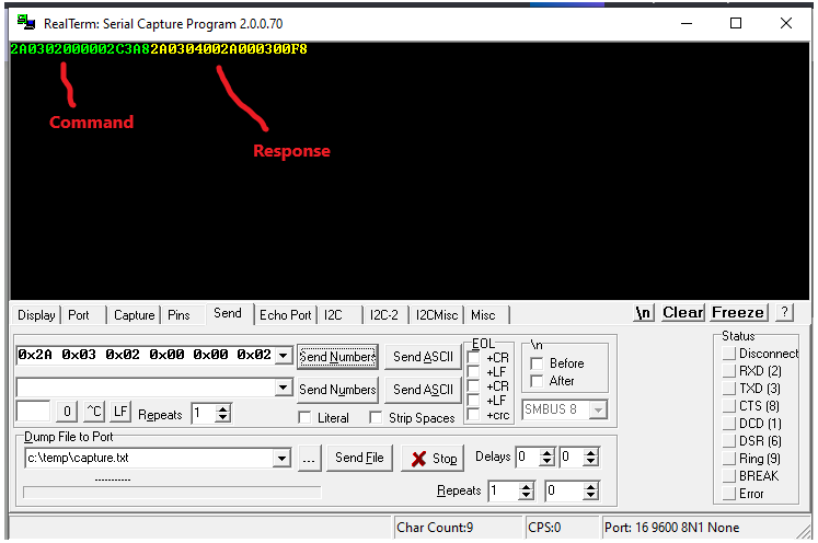
Example 1 (read server address and baud rate code registers)
Command (Client) - “2A0302000002C3A8”
2A server address
03 Modbus function code 3 - read holding registers
02 starting address Hi byte
00 starting address Lo byte
00 quantity of registers Hi byte
02 quantity of registers Lo byte
C3 CRC Hi byte
A8 CRC Lo byte
Response (Server) - “2A0304002A000300F8”
2A server address
03 Modbus function code 3 - read holding registers
04 byte count
002A bytes 1,2 (server address = 2A)
0003 bytes 3,4 (baud rate code = 3 = 9600 baud)
00 CRC Hi byte
F8 CRC Lo byte
Example 2 (read temperature, humidity and dewpoint registers)
Command (Client) - “2A0400000003B610”
2A server address
04 Modbus function code 4 - read input registers)
00 starting address Hi byte
00 starting address Lo byte
00 quantity of registers Hi byte
03 quantity of registers Lo byte
B6 CRC Hi byte
10 CRC Lo byte
Response (Server) - “2A040607310D1400CFF4ED”
2A server address
04 Modbus function code 4 - read input registers
06 byte count
0731 bytes 1,2 (temp = 1841/100 = 18.41C)
0D14 bytes 3,4 (humidity = 3348/100 = 33.48%)
00CF bytes 5,6 (dewpoint = 207/100 = 2.07C)
F4 CRC Hi byte
ED CRC Lo byte
Detailed information on the Modbus communication example is found in section 6.4.2 of the S-TH-1 Air Temperature and HumiditySensor-Data Sheet .
WISE-Studio Software Utility Setup
WISE-Studio is a tool for configuring WISE modules (the utility can be downloaded from WISE Studio). The tool provides a web based interface that is similar across multiple WISE models. For modules configured via Ethernet, LAN, or WLAN, WISE-Studio enables communication with the WISE module’s internal web server. For modules configured via USB (like the WISE-4610), WISE-Studio executes a web server on the computer installed with the software. The web server then uses the USB interface to communicate with the WISE module. The module information can be accessed via the embedded web page or a web browser.
1 - Download and install the USB driver from CP210x USB to UART Bridge VCP Drivers - Silicon Labs.
2 - Download and install WISE Studio from http://support.advantech.com/.
3 - To power the module, connect a DC power source to
the +Vs and -Vs pins.
4 - Connect the module to your computer via the microUSB port.
5 - Open WISE Studio Utility, on Serial Port select Go To Configuration. Then select appropriate COM port and click connect.

Once the PC is connected to the WISE-4610 you can go to the Information page to view module, LoRa, device and power status details. Additional pages include Configuration, I/O Status and Advanced that are used when setting up the 4610. Detailed information on configuring the WISE-4610 can be found in the WISE-4610 User Manual.

Hardware Setup
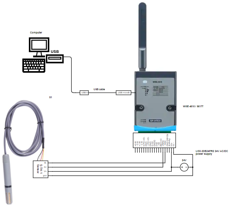
For this project, a 24V DIN rail power supply is used to power the WISE-4610 and a USB cable connected to a PC running WISE Studio. Below schematic diagram illustrates how the setup is implemented and includes a BOM with Digi-Key part numbers (see Scheme-it WISE4610_STH1sensor Project ).
note: USB connection to PC is only used during configuration of the WISE-4610.
Determine WISE-4610 LoRa device EUI, App EUI and App KEY values
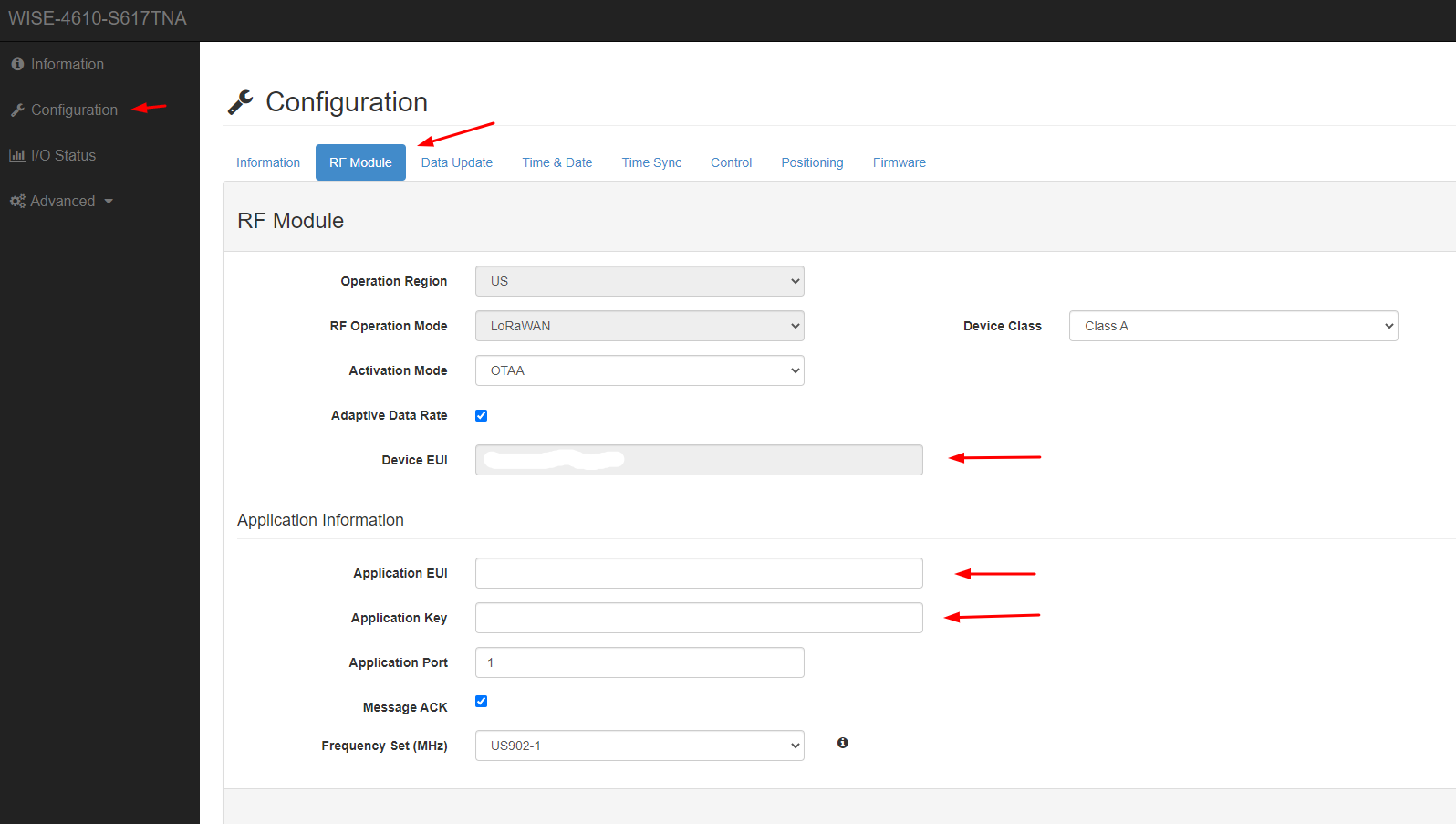
The WISE-4610’s Device EUI, App EUI and App key can be found in WISE Studio by navigating to the RF Module tab of the Configuration page.
note: these LoRa parameters will be needed when adding the 4610 to the Things Stack LoRaWAN network.
Navigate to the IO Status page, select COM1, select ModbusRTU Configuration, and then select Rules Setting tab to specify Modbus command for the S-TH-1 RS-485 humidity/temp sensor with the values:
Slave ID = 42 (0x2A), Type = 04 input register, Start Address = 1, Length = 3, R/W = R, Scan Interval = 60

On the IO Status page, RS-485 rtu sensor data can be viewed on COM1 Status tab and selecting Word Status tab.

Add the WISE-4610 I/O controller to The Things Stack LoRaWAN network server
The Things Stack is an enterprise grade LoRaWAN network server, built on an open source core. The Things Stack allows you to build and manage LoRaWAN networks on your own hardware or in the cloud. The WISE-4610 will be added to The Things Stack server so the I/O data payload of the 4610 can be received by the LoRaWAN server. Since the 4610 data payload consists of a multi character string, it needs to be decoded for the various analog/digital I/O and RS-485 data parameter values using a custom Javascript payload parser. Advantech has developed and provides a general purpose WISE Javascript payload parser that needs to be modified to work with The Things Stack.
This project and below steps assume that a Things Stack LoRaWAN server is running and available to add devices to it’s network.
1 - First step is to login to The Things Stack server as admin.

2 - Select “Applications” and open the application to add the WISE-4610 as an end device (for this project example, farm1 will be used).

3 - In application ID “farm1” select + Add end device.

4 - In Register end device screen, select “Register manually”
For Frequency plan select “United States 902-928 MHz FSB 2(used by TTN)”
For LoRaWAN version select “LoRaWAN Specification 1.0.2”
For Regional Parameters version select “RP001 Regional Parameters 1.0.2”
Enter DevEUI, AppEUI and Appkey parameters as determined by RF Module screen in WISE Studio above.
Once all the data parameters have been entered, select Register end device to complete registration of the WISE-4610.

5 - Next, a payload decoder will need to be set up in The Things Stack to decode the parameter values being sent from the 4610. Advantech provides a reference Javascript payload parser for use with 3rd party LoRaWAN gateways that was modified to work with The Things Stack. The decoder and information on the modifications made can be found on github at LoRaWAN/WISE4610 at main · eewiki/LoRaWAN · GitHub .
6 - To set up the payload decoder in The Things Stack, go to the End device screen for the WISE-4610 (end devices are listed by eui ID). Select the Payload Formatters tab. Under Formatter type select “Custom Javascript formatter”. Copy the Javascript code at github link https://github.com/eewiki/LoRaWAN/blob/main/WISE4610/WiseParserV1_6_8_TTNmod.js and paste in Formatter code window and then select Save changes.

7 - Review LoRaWAN messages for WISE-4610 activity, decoded payload messages will be observable in the Live Data tab. Expand one of the “uplink data” messages to view the rtu payload details.

Example of decoded payload is listed below:
{
  "name": "as.up.data.forward",
  "time": "2023-05-05T20:02:19.191808194Z",
  "identifiers": [
    {
      "device_ids": {
        "device_id": "eui-74fe48ffff7ac6e5",
        "application_ids": {
          "application_id": "farm1"
        },
        "dev_eui": "74FE48FFFF7AC6E5",
        "join_eui": "0000000053363137",
        "dev_addr": "00BA8AE9"
      }
    }
  ],
  "data": {
    "@type": "type.googleapis.com/ttn.lorawan.v3.ApplicationUp",
    "end_device_ids": {
      "device_id": "eui-74fe48ffff7ac6e5",
      "application_ids": {
        "application_id": "farm1"
      },
      "dev_eui": "74FE48FFFF7AC6E5",
      "join_eui": "0000000053363137",
      "dev_addr": "00BA8AE9"
    },
    "correlation_ids": [
      "as:up:01GZPR46A7S6Y0S3DFYPVFKNDQ",
      "gs:conn:01GZMKNRBDVHKGDKECYGGKCBT8",
      "gs:up:host:01GZMKNRGY2P3J4FJT02ZBXE5C",
      "gs:uplink:01GZPR4610PCNW5WBQY34M53SV",
      "ns:uplink:01GZPR4618P1ZYR3RP79SWTD7Y",
      "rpc:/ttn.lorawan.v3.GsNs/HandleUplink:01GZPR4616ZRDSCYMZKDTPV9N5",
      "rpc:/ttn.lorawan.v3.NsAs/HandleUplink:01GZPR46A21WT6ERHB0N4MMWQ5"
    ],
    "received_at": "2023-05-05T20:02:19.079302431Z",
    "uplink_message": {
      "session_key_id": "AYcT4+JJKoHLe7tygE7ZnA==",
      "f_port": 1,
      "f_cnt": 13250,
      "frm_payload": "gcJJAAcHAgAAAAAAAAcnAgAAAAAANAofIP9/AAD//ykCNAo/IP9/AADXj/1/EAIBAIMEAABmCIMEAQAuD4MEAgC0AmAHFgNSxGBVZLk=",
      "decoded_payload": {
        "AI0": {
          "Event": 0,
          "MaxVal": 65535,
          "MinVal": 553,
          "Range": 4,
          "Raw Data": 32767,
          "status": {
            "High Alarm": 0,
            "Low Alarm": 0
          }
        },
        "AI1": {
          "Event": 0,
          "MaxVal": 36823,
          "MinVal": 32765,
          "Range": 4,
          "Raw Data": 32767,
          "status": {
            "High Alarm": 0,
            "Low Alarm": 0
          }
        },
        "DI0": {
          "mode": 0,
          "status": {
            "DI Change": 0,
            "Get/Clean Counter Overflow": 0,
            "Get/Clean H2L Latch": 0,
            "Get/Clean L2H Latch": 0,
            "Signal Logic": 0,
            "Start Counter": 1
          },
          "value": 0
        },
        "DI1": {
          "mode": 0,
          "status": {
            "DI Change": 0,
            "Get/Clean Counter Overflow": 0,
            "Get/Clean H2L Latch": 0,
            "Get/Clean L2H Latch": 0,
            "Signal Logic": 0,
            "Start Counter": 1
          },
          "value": 0
        },
        "DO0": {
          "Mode": "DO",
          "status": {
            "DO Change": 0,
            "Pulse Output Continue": 0,
            "Signal Logic": 0
          }
        },
        "Device": {
          "BatteryLevel": 82,
          "PowerSrc": 3,
          "Time": 1683316932
        },
        "RtuRegister0-0": {
          "Data": 2150,
          "Status": 0
        },
        "RtuRegister0-1": {
          "Data": 3886,
          "Status": 0
        },
        "RtuRegister0-2": {
          "Data": 692,
          "Status": 0
        },
        "SequenceNumber": 194,
        "SourceAddress": null,
        "TotalLength": 73
      },
      "rx_metadata": [
        {
          "gateway_ids": {
            "gateway_id": "dragino24cf29",
            "eui": "A84041FDFE24CF29"
          },
          "time": "2023-05-05T20:02:18.780349Z",
          "timestamp": 1643032564,
          "rssi": -22,
          "channel_rssi": -22,
          "snr": 13.2,
          "frequency_offset": "-10328",
          "uplink_token": "ChsKGQoNZHJhZ2lubzI0Y2YyORIIqEBB/f4kzykQ9N+6jwYaDAjKwdWiBhCuyNz0AiCgov3i6PwQKgwIysHVogYQyNyM9AI=",
          "channel_index": 6
        }
      ],
      "settings": {
        "data_rate": {
          "lora": {
            "bandwidth": 125000,
            "spreading_factor": 7
          }
        },
        "coding_rate": "4/5",
        "frequency": "905100000",
        "timestamp": 1643032564,
        "time": "2023-05-05T20:02:18.780349Z"
      },
      "received_at": "2023-05-05T20:02:18.792508173Z",
      "confirmed": true,
      "consumed_airtime": "0.158976s",
      "network_ids": {
        "net_id": "000000"
      }
    }
  },
  "correlation_ids": [
    "as:up:01GZPR46A7S6Y0S3DFYPVFKNDQ",
    "gs:conn:01GZMKNRBDVHKGDKECYGGKCBT8",
    "gs:up:host:01GZMKNRGY2P3J4FJT02ZBXE5C",
    "gs:uplink:01GZPR4610PCNW5WBQY34M53SV",
    "ns:uplink:01GZPR4618P1ZYR3RP79SWTD7Y",
    "rpc:/ttn.lorawan.v3.GsNs/HandleUplink:01GZPR4616ZRDSCYMZKDTPV9N5",
    "rpc:/ttn.lorawan.v3.NsAs/HandleUplink:01GZPR46A21WT6ERHB0N4MMWQ5"
  ],
  "origin": "0204e7fb6077",
  "visibility": {
    "rights": [
      "RIGHT_APPLICATION_TRAFFIC_READ"
    ]
  },
  "unique_id": "01GZPR46DQJ76TKCPF1Z0KMW9Q"
}
Adding Applications and Integrations
Once the WISE-4610 has been configured and added to The Things Stack LoRaWAN network server the data being uplinked/downlinked from/to the WISE-4610 can be acted upon and/or visualized by adding Applications and Integrations. Many options can be implemented including MQTT, Node-RED, IFTTT, Cloud and others. Additional information can be found at Integrations | The Things Stack for LoRaWAN .
Accessing The Things Stack MQTT Server
The Things Stack exposes an MQTT server to work with streaming events. The following steps describe how to connect an MQTT client and subscribe to uplinks or publish downlinks. Machinechat JEDI will need the MQTT server information in order to receive the streaming S2101 sensor data. Detailed information on The Things Stack MQTT server can be found at MQTT Server | The Things Stack for LoRaWAN .
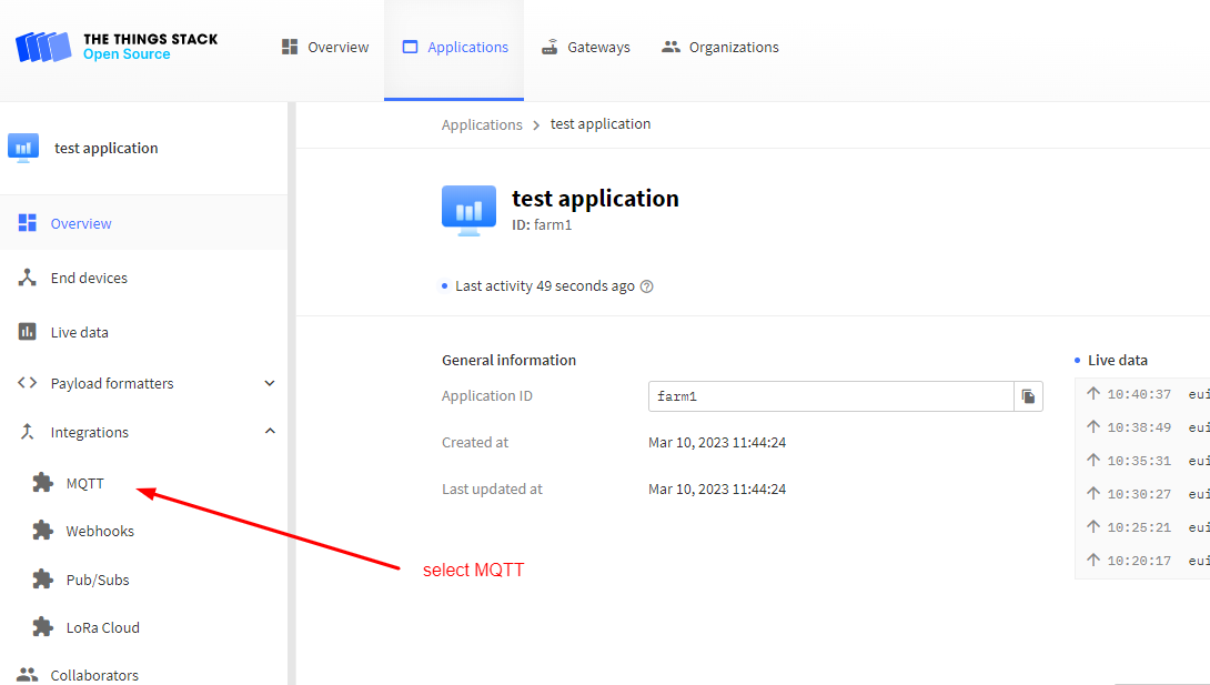
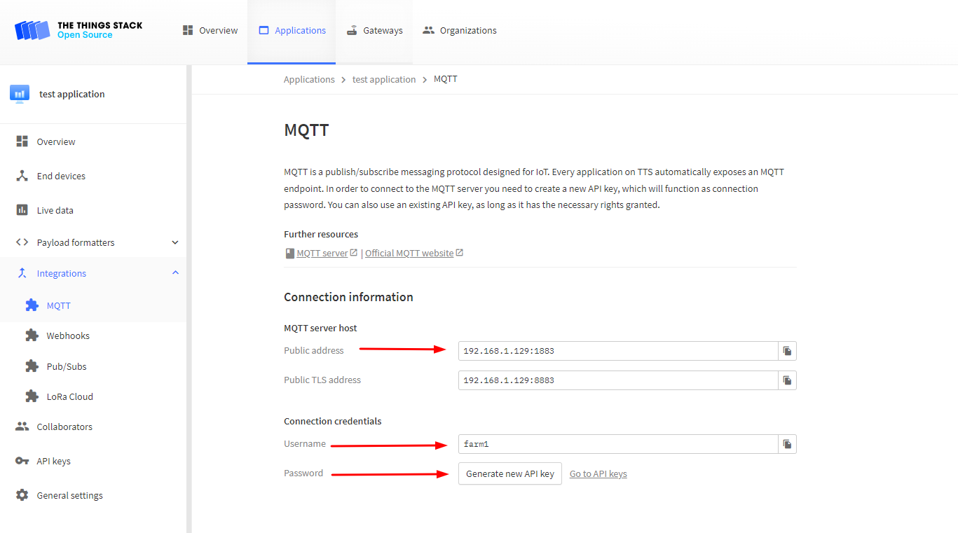
1 - Creating an API Key. In order to use the MQTT server a new API key needs to be generated to authenticate. The Console provides the required connection information and can be used to create an API key for authentication. In your Applications tab select the MQTT submenu from the Integrations side menu.
2 - Click on the Generate new API key button to generate an API key for use in connecting to the MQTT server. Make note of the MQTT info which is needed for the JEDI data collector configuration file (Public address, Username, Password).

Setting up Machinechat JEDI Pro MQTT Custom Data Collector
A custom MQTT data collector will be set up on JEDI Pro to subscribe to the sensor data from the WISE-4610 I/O module. The data collector consists of two files, “dcollector.bin” is the executable file that is run on the machine running JEDI and “dconfig.yml” is the corresponding configuration file containing the pertinent MQTT and sensor info. For this project, the temperature and humidity values of the S2101 will be subscribed to by editing dconfig.yml with the sensor parameter names. To determine the sensor parameter names, the LoRaWAN data payload for the LHT65N will be reviewed.
1 - Download the 32-bit arm7 version of the LoRaWAN MQTT data collector “dcollector.bin” and configuration file “dconfig.yml” from Machinechat at link https://support.machinechat.io/hc/en-us/articles/13935227926935-TTN-MQTT-LoRaWAN-Collector .
2 - Review the WISE-4610 LoRaWAN payload. As noted above, the payload includes the below data.

The temperature parameter is “RtuRegister0-0.Data”, humidity parameter is "RtuRegister0-1.Data”, and dew point parameter is “RtuRegister0-2.Data”.
3 - The configuration file needs to be modified with the MQTT info and sensor data parameters. The values that need to be modified are:
mQTTBrokerFullURL: this is “Public Address” from above MQTT Integration
mQTTUsername: this is “Username” from above MQTT Integration
mQTTPassword: this is “Password” from above MQTT Integration
cSproperty: this is parameter subscribed to in the LoRa payload
mcProperty: this is the corresponding parameter name mapped in JEDI
Example dconfig.yml file
mQTTBrokerFullURL: "tcp://192.168.1.129:1883"
mQTTUsername: "farm1"
mQTTPassword: "NNSXS.XFQCW3GFJXGC78MPOVKF3M2CUD4HFNSHNZQLRJQ.MB5VAGIGLVQ3F66LFYK2CVY2Z66A4CWRLQJXRIQBNT1A8IH7C6TA"
sendTestSenML: true
# setDebugLevel 0 is no debug, 1 is colorized JSON decode, 2 is 1 plus verbose payload dumps
setDebugLevel: 1
propertyNames:
 - cSproperty: "Device.BatteryLevel"
    mcProperty: "Battery"
  - cSproperty: "DI0.value"
    mcProperty: "DI0value"
  - cSproperty: "DI1.value"
    mcProperty: "DI1value"
  - cSproperty: "AI0.Raw Data"
    mcProperty: "AI0volt"
    transform: "round(data - 32767)/3277"
    precision: 2
  - cSproperty: "AI1.Raw Data"
    mcProperty: "AI1RawData"
  - cSproperty: "RtuRegister0-0.Data"
    mcProperty: "SHT1data0"
    transform: "round(data)/100"
    precision: 2
  - cSproperty: "RtuRegister0-1.Data"
    mcProperty: "SHT1data1"
    transform: "round(data)/100"
    precision: 2
  - cSproperty: "RtuRegister0-2.Data"
    mcProperty: "SHT1data2"
    transform: "round(data)/100"
    precision: 2
4 - Install the data collector “dcollector.bin” and configuration “dconfig.yml” files by copying them to the “jedi/plugins” directory of the machine where JEDI is installed.
5 - Test the data collector by running “./dcollector.bin ./dconfig.yml” on the command line in the jedi/plugins directory. Below is example of some of the output data on the terminal when the data collector is working correctly (debug level set to 1).
{
    "AI0.Event": 0,
    "AI0.MaxVal": 32768,
    "AI0.MinVal": 32766,
    "AI0.Range": 4,
    "AI0.Raw Data": 32767,
    "AI0.status.High Alarm": 0,
    "AI0.status.Low Alarm": 0,
    "AI1.Event": 0,
    "AI1.MaxVal": 32768,
    "AI1.MinVal": 32767,
    "AI1.Range": 4,
    "AI1.Raw Data": 32768,
    "AI1.status.High Alarm": 0,
    "AI1.status.Low Alarm": 0,
    "DI0.mode": 0,
    "DI0.status.DI Change": 0,
    "DI0.status.Get/Clean Counter Overflow": 0,
    "DI0.status.Get/Clean H2L Latch": 0,
    "DI0.status.Get/Clean L2H Latch": 0,
    "DI0.status.Signal Logic": 0,
    "DI0.status.Start Counter": 1,
    "DI0.value": 0,
    "DI1.mode": 0,
    "DI1.status.DI Change": 0,
    "DI1.status.Get/Clean Counter Overflow": 0,
    "DI1.status.Get/Clean H2L Latch": 0,
    "DI1.status.Get/Clean L2H Latch": 0,
    "DI1.status.Signal Logic": 0,
    "DI1.status.Start Counter": 1,
    "DI1.value": 0,
    "DO0.Mode": "DO",
    "DO0.status.DO Change": 0,
    "DO0.status.Pulse Output Continue": 0,
    "DO0.status.Signal Logic": 0,
    "Device.BatteryLevel": 82,
    "Device.PowerSrc": 3,
    "Device.Time": 1684181570,
    "RtuRegister0-0.Data": 25.19,
    "RtuRegister0-0.Status": 0,
    "RtuRegister0-1.Data": 26.56,
    "RtuRegister0-1.Status": 0,
    "RtuRegister0-2.Data": 4.64,
    "RtuRegister0-2.Status": 0,
    "SequenceNumber": 89,
    "SourceAddress": null,
    "TotalLength": 73
}
6 - Open JEDI and navigate to “Settings” and then select “Data Collectors”. Click on “Add Collector” to add new data collector.

7 - Add new data collector. Enter data collector name, select “Custom Plug-in” for type, select “dcollector.bin” for Plug-in Executable, add dconfig.yml file location for Plug-in Options, select “Run As Background Process and Monitor”, click on "“VALIDATE PLUG IN” and then select “SAVE” to save settings.

Displaying the LoRaWAN WISE-4610 / RS-485 temperature & humidity sensor data on JEDI Pro.
In JEDI, navigate to “Data Dashboard” and create new charts for WISE-4610 / RS-485 temperature & humidity sensor. Example dashboard is shown below.

Conclusion
The Advantech WISE-4610P-NA paired with the S617T I/O module provides multiple I/O data capability for sensing and control of digital/analog signals and RS-485 devices over LoRaWAN. The benefit of supporting RS-485/Modbus communication allows a large diverse variety of sensors and controls to interface with the WISE-4610. Having the data available in The Things Stack LoRaWAN network server provides the opportunity for visualizing and acting on the data by throught the use of MQTT integration. Setting up a custom data collector in Machinechat JEDI Pro provides access to the WISE4610 sensor data for visualization and actioning.
References
- Digi-Key TechForum - Getting Started with Advantech’s WISE-4610 Industrial LoRaWAN I/O Module
- Digi-Key TechForum - Getting Started with machinechat’s JEDI One IoT Platform
- Advantech - WISE-4610 product page
- Advantech - WISE-S617T product page
- Advantech - WISE-4610 User Manual
- Advantech - WISE-4610 Startup Manual
- Advantech - IAG_FAQ WISE-2000 How to receive LoRa end node data payload and parse data on TTN_20200312.pdf
- Advantech - WISE-4610 FAQ
- Seeed - Product Model: S-TH-01, RS485-Industrial-grade air temperature and humidity sensor
- Machinechat - Building a private, edge-based LoRaWAN IoT sensor network
- The Things Network - The Things Stack documentation
https://support.machinechat.io/hc/en-us/articles/4413766942615-Building-a-private-edge-based-LoRaWAN-IoT-sensor-network