Description
There are many Modbus/RS485 applications and installations that could benefit from a wireless interface to RS485 devices and hardware. For RS485 devices with small data payloads that report intermittently, the LoRa wireless protocol is a good choice that provides benefits of long range and low power.
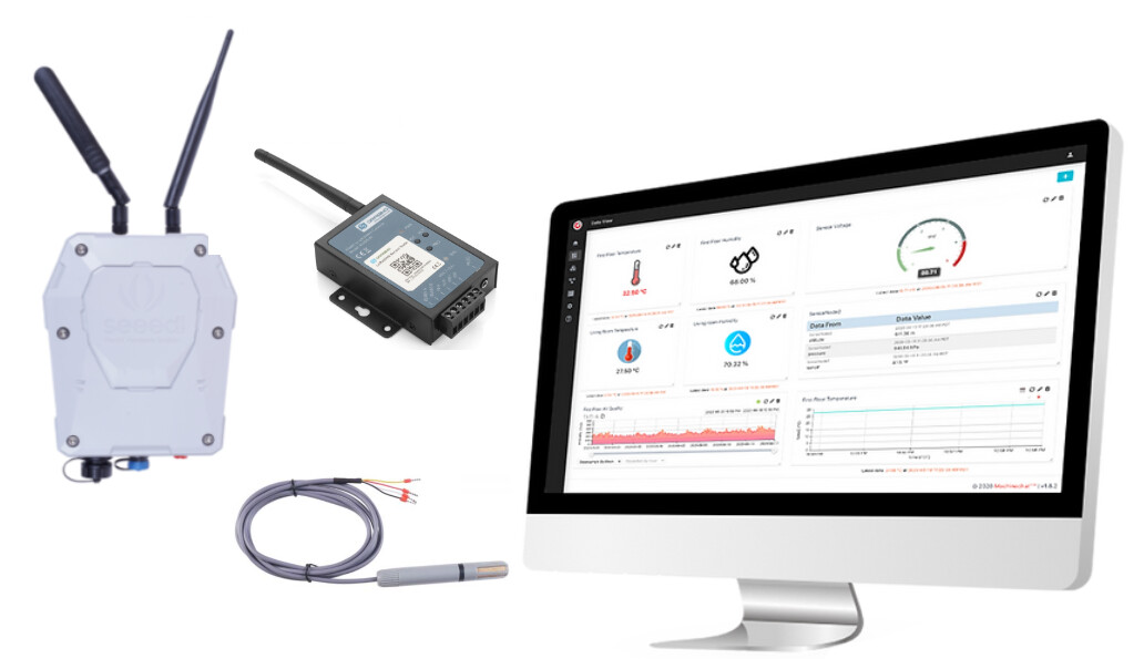
Dragino’s RS485-LN provides the means of connecting to various RS485 sensors and hardware, sending customized Modbus commands to read/control the RS485 devices, and uploading the resulting RS485 data/information to a LoRaWAN network. For this project the RS485-LN and Seeed’s S-TH-1 RS485 Temperature/Humidity Sensor are set up and configured to query the sensor and upload temperature and humidity data over LoRa.
The project also discusses adding the sensor node to an existing ChirpStack based private LoRaWAN network and Machinechat’s JEDI Pro IoT software platform. The LoRaWAN network uses Seeed’s IP67 rated industrial LoRaWAN gateway to forward the LoRa sensor packets to a private ChirpStack LoRaWAN network server running on a Seeed’s ReServer (with Ubuntu linux installed). Machinechat’s JEDI Pro IoT platform runs on the same ReServer.
Hardware
- Seeed reServer
reServer is based on an ODYSSEY X86 v2 board and powered by Intel® Core™ 11th Gen. i3 and Intel UHD Graphics 48EUs - Seeed SenseCAP Outdoor Gateway - LoRaWAN US915MHz
SenseCAP LoRaWAN Gateway is based on LoRaWAN® protocol, applicable for low-power, long-distance environmental data collection and monitoring. - Dragino RS485-LN
Dragino RS485 to LoRaWAN Converter (SX1276) RS485-LN-US915MHz - Seeed S-TH-01 Temperature and Humidity Sensor
Industrial RS485 Air Temperature and Humidity Sensor - Waveshare USB TORS232/485/TTL
Industrial USB to RS232/485/TTL isolated converter
Software
- JEDI Pro or JEDI Pro SSE
Adaptable software for IoT data collection, visualization, monitoring and data storage that can be integrated into IoT solutions. Capabilities include: collect data from sensors, devices and machines; build intuitive real-time and historical data and system view dashboards; create rules to monitor and respond to data conditions automatically; receive alert notifications by email and SMS. JEDI Pro SSE is the Seeed Studio Edition version of JEDI Pro that adds a Data Collector for Seeed’s line of SenseCAP LoRaWAN sensors - ChirpStack
The ChirpStack open-source LoRaWAN Network Server stack provides open-source components for LoRaWAN networks. The modular architecture makes it possible to integrate within existing infrastructures. - Modbus
The Modbus Organization is a group of independent users and suppliers of automation devices that seeks to drive the adoption of the Modbus communication protocol suite and the evolution to address architectures for distributed automation systems across multiple market segments.
Background
This post is a follow-on project that builds on the related TechForum post Set up a private LoRaWAN Sensor Network with Machinechat and Seeed SenseCAP which details setting up a private LoRaWAN IoT sensor network using off the shelf hardware and software available at Digi-Key. Software used in the related project included Machinechat’s JEDI Pro applications software and ChirpStack’s LoRaWAN network server application. Hardware used in the project included a Seeed reServer x86 server and SenseCAP outdoor LoRaWAN gateway. For this project a Dragino RS485-LN is used to read the temperature, humidity and dewpoint registers of the Seeed S-TH-1 sensor and upload the sensor data over a LoRaWAN network.

Dragino RS485-LN
The Dragino RS485-LN is a RS485 to LoRaWAN Converter that converts RS485 data into long range wireless LoRa payloads and transmits to a LoRaWAN gateway. For data uplink, the RS485-LN is configured to send user-defined commands to RS485 devices it is connected to and read their responses. The RS485-LN then processes the responses according to user-defined rules to build a data payload to upload over LoRa to the LoraWAN server. For data downlink, the RS485-LN runs in LoRaWAN Class C to receive RS485/Modbus commands. When there are downlink commands from the LoRaWAN server, the RS485-LN forwards the commands from the LoRaWAN server to the RS485 devices it is connected to. The RS485-LN allows user to monitor / control RS485 devices and reach extremely long ranges. It provides ultra-long range spread spectrum communication and high interference immunity while minimizing current consumption.

Seeed S-TH-1 RS485 Temperature/Humidity Sensor
The S-TH-01 module provides industrial-grade sensing and compact air temperature and humidity sensing in one small-size sensor. The S-TH-1 is powered by a 3.6-30V DC supply and communication is over RS485 following Modbus protocol.
Testing RS485 Sensor Communication
It is always a good practice to test the RS485 communication with sensor being used. This is accomplished by using RealTerm serial terminal running on a Windows PC that is connected to a USB to RS485 converter connected over RS485 to the sensor being tested. For this project a Waveshare USB to RS232/485/TTL converter is used to connect to the Seeed temperature/humidity sensor as shown in Scheme-it drawing SeeedSTH1TempRS485Test below:

Once the sensor is wired up and powered, start RealTerm and connect to COM port connected to the Waveshare USB to RS232/485/TTL converter. RS485 communication can be tested by sending the sensor a valid command and monitoring the response. note: the address of the sensor is located on a label attached to the sensor cable and happens to be decimal 42 (hex 0x2A).
Select the “Send” tab and enter the Modbus command as hex values and select “Send Numbers”. In the below example the command is “2A0302000002C3A8” (read server address and baud rate code registers)
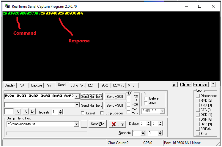
Example 1 (read server address and baud rate code registers)
Command (Client) - “2A0302000002C3A8”
2A server address
03 Modbus function code 3 - read holding registers
02 starting address Hi byte
00 starting address Lo byte
00 quantity of registers Hi byte
02 quantity of registers Lo byte
C3 CRC Hi byte
A8 CRC Lo byte
Response (Server) - “2A0304002A000300F8”
2A server address
03 Modbus function code 3 - read holding registers
04 byte count
002A bytes 1,2 (server address = 2A)
0003 bytes 3,4 (baud rate code = 3 = 9600 baud)
00 CRC Hi byte
F8 CRC Lo byte
Example 2 (read temperature, humidity and dewpoint registers)
Command (Client) - “2A0400000003B610”
2A server address
04 Modbus function code 4 - read input registers)
00 starting address Hi byte
00 starting address Lo byte
00 quantity of registers Hi byte
03 quantity of registers Lo byte
B6 CRC Hi byte
10 CRC Lo byte
Response (Server) - “2A040607310D1400CFF4ED”
2A server address
04 Modbus function code 4 - read input registers
06 byte count
0731 bytes 1,2 (temp = 1841/100 = 18.41C)
0D14 bytes 3,4 (humidity = 3348/100 = 33.48%)
00CF bytes 5,6 (dewpoint = 207/100 = 2.07C)
F4 CRC Hi byte
ED CRC Lo byte
Detailed information on the Modbus communication example is found in section 6.4.2 of the S-TH-1 Air Temperature and HumiditySensor-Data Sheet.
Setting up the RS485-LN for RS485 and LoRa Communication
For this project the RS485-LN needs to be configured to send send the appropriate Modbus command over RS485 to the S-TH-1 sensor to read the input registers for temperature, humidity and dew point. Next, it needs to be configured to build an appropriate data payload to uplink over LoRa to the LoRaWAN gateway. To configure the RS485-LN it needs to be powered and a serial terminal connected via the programming cable as shown in below Scheme-it drawing DraginoRS485LN_ProgramCable.

Electrical connections are listed in below table:
| RS485-LN | FTDI serial cable | Power Supply | Computer |
|---|---|---|---|
| Vin- | - | GND | - |
| Vin+ | - | +12VDC | - |
| PRO-txd (red) | 4 - tx (orange) | - | - |
| PRO-rxd (white) | 5 - rx (yellow) | - | - |
| PRO-gnd (black) | 1 - gnd (black) | - | - |
| - | USB | - | USB |
For this project the RS485-LN is connected to a single RS485 device, Seeed S-TH-1 sensor, and needs to be configured to send the appropriated RS485 command to read the temperature, humidity and dewpoint registers and build a data payload to be sent over LoRa to the LoRaWAN server. Both the RS485-LN user manual and S-TH-1 data sheet are important reference documents to be used when configuring the RS485-LN.
1 - Configure the RS485-LN for Modbus command.
The RS485-LN uses the “AT+COMMANDx=x y z …” command type to create RS485 commands to be sent to the RS485 devices it is connected to. Since there is only the one S-TH-1 RS485 device, the command is “AT+COMMMAND1= 2A 04 00 00 00 03,1”
| Value | Description |
|---|---|
| 2A | server address |
| 04 | Modbus function code 4 - read input registers |
| 00 | starting address Hi byte |
| 00 | starting address Lo byte |
| 00 | quantity of registers Hi byte |
| 03 | quantity of registers Lo byte |
| 1 | add CRC-16/MODBUS to the end of the command |
2 - Configure the RS485-LN to build an appropriate data payload from the S-TH-1 sensor response.
The RS485-LN uses the “AT+DATACUTx=x,y,z …” command type to build the data payload of the sensor response to be uploaded over LoRa. Since there is only the one S-TH-1 RS485 device connected and the command response is 11 bytes log, the command used is “AT+DATACUT1=11,2,1~11” (uploads all bytes from the command response)
| Value | Description |
|---|---|
| 11 | length (in bytes) for the response of AT+COMMAND |
| 2 | grab valid value by bytes section |
| 1~11 | define the position for valid value (bytes 1 through 11) |
3 - Configure the RS485-LN parameters for payload version, sampling rate and upload configuration.
For this project, set “AT+PAYVER=9” (payload version 9), “AT+TDC=60000” (sampling time delay 60 seconds), “AT+DATAUP=0” (upload data in single uplink)
Setting up and testing the S-TH-1 and RS485-LN for LoRa communication
Connect the programming cable to a serial terminal and the RS485-LN program connector. The RS485-LN A+, B-, RS485gnd and power terminals are connected to the S-TH-1 sensor as shown in the below drawing. Both the RS485-LN and S-TH-1 are powered by the same 12VDC power supply.
(see Scheme-it Project: DraginoRS485_SeeedSTH1_Pcable.

Determine RS485-LN device EUI and APPKEY
Use TeraTerm (or similar serial terminal program) and FTDI USB to TTL adaptor connected to the program cable as shown above. Once connected, enter the “123456” password and then “AT+CFG” to print the configuration data (includes device EUI and APPKEY). note: see below example data
AT+DEUI=a8 40 41 b1 31 84 7d fa
AT+DADDR=01847DFA
AT+APPKEY=12 34 56 78 90 1a 1b 1c 1d 1f 2a 2b 2c 2d 2e 2f
AT+NWKSKEY=cb ee cf 7c 9d c4 d1 9f c4 64 26 b9 2b d7 8d 91
AT+APPSKEY=f8 d9 c9 a9 f6 55 12 cb fd 5b ab 74 36 ec 62 f1
AT+APPEUI=a8 40 41 00 00 00 01 01
AT+ADR=1
AT+TXP=5
AT+DR=1
AT+DCS=0
AT+PNM=1
AT+RX2FQ=923300000
AT+RX2DR=8
AT+RX1DL=1000
AT+RX2DL=2000
AT+JN1DL=5000
AT+JN2DL=6000
AT+NJM=1
AT+NWKID=00 00 00 00
AT+FCU=698
AT+FCD=740
AT+CLASS=C
AT+NJS=1
AT+RECVB=0:
AT+RECV=0:
AT+VER=v1.3 US915
AT+CFM=0
AT+CFS=0
AT+SNR=0
AT+RSSI=0
AT+RJTDC=20
AT+RPL=4
AT+TDC=60000
AT+PORT=2
AT+RX1WTO=24
AT+RX2WTO=7
AT+INTMOD=2
AT+PWORD=123456
AT+MBFUN=0
AT+BAUDR=9600
AT+PARITY=0
AT+STOPBIT=0
AT+DATAUP=0
AT+PAYVER=9
AT+CHS=0
AT+CHE=0
Use default channel
AT+COMMAND1=2a 04 00 00 00 03 ,1     AT+DATACUT1=11,2,1~11     AT+CMDDL1=0
AT+COMMAND2=0,0     AT+DATACUT2=0,0,0     AT+CMDDL2=0
AT+COMMAND3=0,0     AT+DATACUT3=0,0,0     AT+CMDDL3=0
AT+COMMAND4=0,0     AT+DATACUT4=0,0,0     AT+CMDDL4=0
AT+COMMAND5=0,0     AT+DATACUT5=0,0,0     AT+CMDDL5=0
AT+COMMAND6=0,0     AT+DATACUT6=0,0,0     AT+CMDDL6=0
AT+COMMAND7=0,0     AT+DATACUT7=0,0,0     AT+CMDDL7=0
AT+COMMAND8=0,0     AT+DATACUT8=0,0,0     AT+CMDDL8=0
AT+COMMAND9=0,0     AT+DATACUT9=0,0,0     AT+CMDDL9=0
AT+COMMANDA=0,0     AT+DATACUTA=0,0,0     AT+CMDDLA=0
AT+COMMANDB=0,0     AT+DATACUTB=0,0,0     AT+CMDDLB=0
AT+COMMANDC=0,0     AT+DATACUTC=0,0,0     AT+CMDDLC=0
AT+COMMANDD=0,0     AT+DATACUTD=0,0,0     AT+CMDDLD=0
AT+COMMANDE=0,0     AT+DATACUTE=0,0,0     AT+CMDDLE=0
AT+COMMANDF=0,0     AT+DATACUTF=0,0,0     AT+CMDDLF=0
Add the RS485-LN to the ChirpStack LoRaWAN network server
(note: this project and below steps assume that a ChirpStack based private LoRaWAN network is active and in range of the LoRa-E5 sensor node, if not refer to TechForum post Set up a private LoRaWAN Sensor Network with Machinechat and Seeed SenseCAP)
1 - In ChirpStack, select Device-profile and Create. Name Device-profile “DraginoRS485LN”, Select “1.0.3” for LoRaWAN MAC version, Select “A” for LoRaWAN Regional Parameters version, Select “Default ADR algorithm” for ADR algorithm, and enter “3600” for Uplink interval. In JOIN(OTAA/ABP) tab, check box for “Device supports OTAA”.

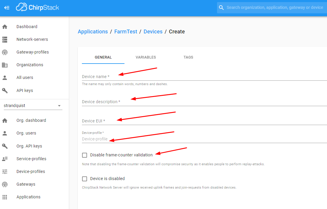
2 - In ChirpStack, select Applications, then select “FarmTest” and then select Create. Enter “DraginoRS485LN” for Device name, enter “description” for Device description, enter Device EUI for RS485-LN (determined from above step “Determine RS485-LN device EUI and APPKEY”), enter “DraginoRS485LN” for Device-profile, and select CREATE DEVICE. (note: for initial testing and demonstration you may want to check Disable frame-counter validation box)
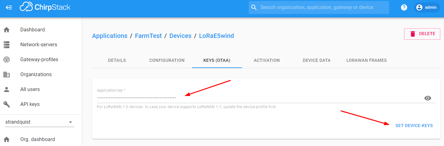
3 - Add Application key for Device. Enter Application key APPKEY from above step “Determine RS485-LN device EUI and APPKEY” and select SET DEVICE-KEYS.
Once the DEVICE-KEYS are set, the RS485-LN should join the LoRaWAN network and start uploading sensor data payloads. You can check by going to “Applications/FarmTest” to see if the RS485-LN has joined ChirpStack:

Once the RS485-LN has joined, you can view it’s “DEVICE DATA” by expanding one of the messages:

Below expanded “DEVICE DATA” example shows the base64 encoded data payload:

Develop and add CODEC to ChirpStack Device Profile
In order for ChirpStack to decode more meaningful information from the data payload, a CODEC has to be specified in the DraginoRS485LN device profile. Since the RS485-LN can be used for nearly any RS485 device type and multiple devices, a custom Java script CODEC needs to be developed specifically for the RS485-LN / S-TH-1 sensor data payload and saved in the Device Profile.
1 - First step is to decode an example base64 encoded payload to determine the data parameters and associated position in order to develop the codec. An example encoded payload can be copied from the DraginoRS485LN “Device DATA” and decoded using an online base64 to hex decoder such as https://www.asciitohex.com/. An example encoded payload is “CSoEBgbnEB8BtIrz”. This is decoded to the hex byte sequence “09 2a 04 06 06 e7 10 1f 01 b4 8a f3”. Reviewing the “AT+DATACUT” command used in the RS485-LN configuration this translate to the following:
| Value | Byte | Description |
|---|---|---|
| 09 | 0 | payload version |
| 2a | 1 | server address |
| 04 | 2 | Modbus function code 4 - read input registers |
| 06 | 3 | byte count |
| 06 e7 | 4,5 | bytes 1,2 (temp = 1767/100 = 17.67 C |
| 10 1f | 6,7 | bytes 3,4 (humidity = 4127/100 = 41.27% |
| 01 b4 | 8,9 | bytes 5,6 (dew point = 436/100 = 4.36 C |
| 8a | 10 | CRC Hi byte |
| f3 | 11 | CRC Lo byte |
2 - For purposes of this project the below codec was developed to decode the payload version, hardware, temperature, humidity and dew point values from the payload.
// Decode decodes an array of bytes into an object.
//  - fPort contains the LoRaWAN fPort number
//  - bytes is an array of bytes, e.g. [225, 230, 255, 0]
//  - variables contains the device variables e.g. {"calibration": "3.5"} (both the key / value are of type string)
// The function must return an object, e.g. {"temperature": 22.5}
function Decode(fPort, bytes) {
    //Payload Formats of RS485LN with S-TH-1 sensor or Unknown HW
  	  var hardware= ((bytes[0])>>3 & (bytes[1])>>5);
      var decode = {};

      if(hardware=='1')
      {
        decode.Hardware="RS485LN_STH1";
        decode.PayloadVer = parseFloat((bytes[0]).toFixed());
        decode.STH1_temp= parseFloat(((bytes[4]<<24>>16 | bytes[5])/100).toFixed(3));
        decode.STH1_humid= parseFloat(((bytes[6]<<24>>16 | bytes[7])/100).toFixed(3));
        decode.STH1_dewpt= parseFloat(((bytes[8]<<24>>16 | bytes[9])/100).toFixed(3));
      }
      else
      {
        decode.Hardware= "Unknown HW";
      }


      if(bytes.length==12)
      {
        return decode;
      }
    }
3 - Test the codec
Go to “Device Profiles” and select “Dragino RS485LN”. Select “CODEC” and paste above Javascript code into decode section and select “UPDATE-DEVICE PROFILE”. Now open “Applications/FarmTest/Devices/DraginoRS485LN” and view “DEVICE DATA”. Open a frame and you should see the encoded and decoded JSON data as shown below.

Set up and test ChirpStack HTTP Integration with JEDI Pro Generic LoRaWAN Custom Data Collector
ChirpStack is modified to add HTTP integration for forwarding LoRaWAN meta and sensor data to a specified IP address. Machinechat’s Generic LoRaWAN Custom Data Collector Plug-in is used for listening to the specified IP address and parsing the LoRaWAN data for review (when debug enabled) and use in the JEDI Pro platform.
(note 1: The Custom Data Collector consists of two files, lorawan-linux.bin and config.yml that are available from Machinechat at: https://support.machinechat.io/hc/en-us/articles/6046199010327-Generic-LoRaWAN-Custom-Data-Collector-Beta-for-JEDI-PRO-Linux )
(note 2: if you have previously set up ChirpStack HTTP integration on your system, you can skip sections 1-4 and go directly to step 5)
1 - Enable HTTP Integration in ChirpStack.
Select “Add” in ChirpStack Integrations screen.

2 - Configure HTTP Integration
Select “JSON” for Payload marshaler , add IP address (use same IP as in config.yml file) for Endpoint URL , and select ADD INTEGRATION

3 - Copy lorawan-linux.bin and config.yml files to the ~/jedi/plugins directory where JEDI Pro is installed on the Ubuntu Linux Mini-PC. Modify config.yml file to enable debug and specify IP listening address.
(note: if you have previously installed the lorawan-linux.bin and config.yml files for a different sensor, all you need to do is edit config.yml as shown in step 5 to add the info for the S-TH-! sensor temperature, humidity and dew point parameters).

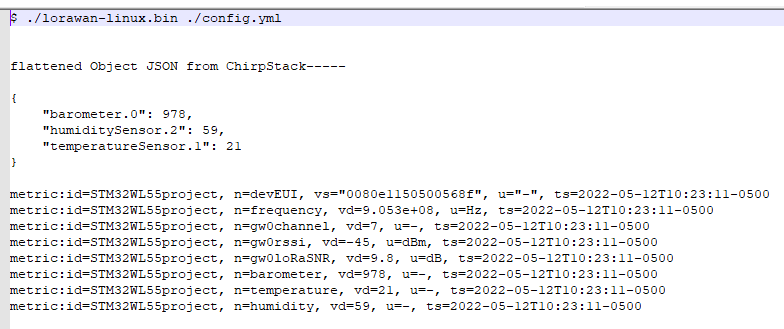
4 - Run Custom Plug-In on command line using “./lorawan-linux.bin ./config.yml” on terminal in Ubuntu Linux Mini-PC and monitor output data. Data should look similar to below (note: remember to make lorawan-linux.bin file executable):
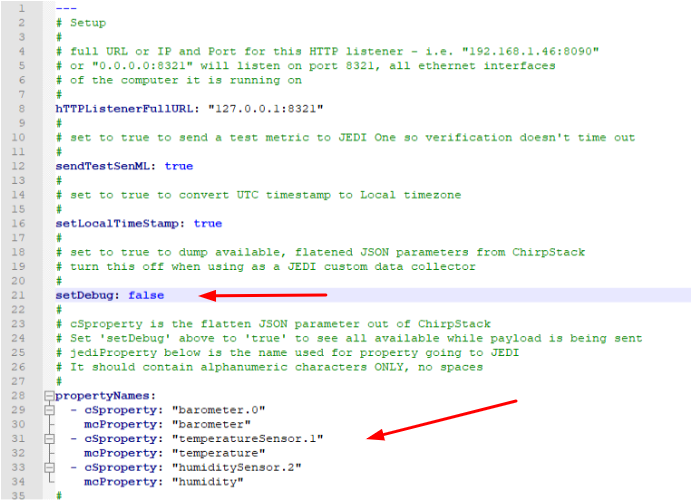
5 - Edit config.yml file to map LoRaWAN data to JEDI Pro data parameters and disable debug. For this project example, edit propertyNames so LoRaWAN cSproperty: “SHT1_temp” is mapped to mcProperty: “SHT1temperature” and LoRaWAN cSproperty: “SHT1_humid” is mapped to mcProperty: “SHT1humidity” and LoRaWAN cSproperty: “SHT1_dewpt” is mapped to mcProperty: “SHT1dewpoint”. Disable debugging by setting “setDebug:” to false and save file.
Set up JEDI Pro Custom Data Collector and Data Dashboard
In JEDI Pro, select “Settings” tab, then select “Data Collectors” and select “Add Collector”. (note: if you have previously added the LoRaWAN custom data collector to your JEDI application this step is not necessary)

Configure Collector as shown below. Name Data Collector “LoRaWAN” (or whatever you prefer), select Collector Type as “Custom Plug-In”, select “lorawan-linux.bin” as Plug-In Executable file, enter location of config.yml file (example: “/home/scottr/jedi/plugins/config.yml” for Plug-in Options, select check box for “Run As Background Process and Monitor” , then select “VALIDATE PLUG-IN” to verifiy functionality.

In JEDI Pro, select “Data Dashboards”, then select “+” to add a new chart. Configure data charts for STH1 temperature, humidity, dewpoint and select “Add” to include in your Data Dashboard.

Conclusion
The RS485LN significantly expands the capabilities of a private LoRaWAN to add nearly any type of RS485/Modbus sensor or device. Another potential benefit would be to add a wireless LoRaWAN network and IoT software platform data collection, visualization, monitoring and data storage capability to an existing RS485/Modbus installation. The project example can easily be expanded and modified for other sensors, applications and use cases as needed.
References
- Seeed - Getting Started with reServer
- Seeed - SenseCAP Outdoor Gateway - LoRaWAN US915MHz
- Seeed - Product Model: S-TH-01, RS485-Industrial-grade air temperature and humidity sensor
- Dragino - RS485-LN – RS485 to LoRaWAN Converter User Manual
- Sparkfun - Serial Terminal Basics
- Getting Started with machinechat’s JEDI One IoT Platform
- Machinechat - Building a private, edge-based LoRaWAN IoT sensor network